I started this thread for IRFP240 Quasi: https://www.diyaudio.com/community/threads/quasi-irfp240-amplifier.428495/
Now I use another MOSFET transistor for better qualities.
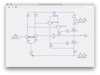
I use Exicon Lateral ECX10N20 for this thread.
The benefits are three:
1. Somewhat less distortion, THD 0.005%
2. Higher max output, 25 Watt in 8 Ohm
3. No need for MOSFET protection diodes, are already built in
Here is the schematic. Enjoy 🙂

Now I use another MOSFET transistor for better qualities.
I use Exicon Lateral ECX10N20 for this thread.
The benefits are three:
1. Somewhat less distortion, THD 0.005%
2. Higher max output, 25 Watt in 8 Ohm
3. No need for MOSFET protection diodes, are already built in
Here is the schematic. Enjoy 🙂

lineup, you do not specify at what power the distortion is given. Also, you are not looking at my pictures carefully. Look at the transistor currents. It can be seen that the circuit is very asymmetrical, one of the transistors works almost like a current generator with a load power of 1 watt. The upper transistor won't close!

In order to get 25 watts of output, I increased the input signal 5 times. I didn't get 25 watts, the circuit was limited.

In order to get 25 watts of output, I increased the input signal 5 times. I didn't get 25 watts, the circuit was limited.
Your topology only works for conventional power mosfets, not the lateral mosfets.Let's go further.
Lateral mosfets have low gm, about 2A per volt. Let's say the threshold voltage is 1V. Thus, it needs 2Vgs to get 2A output. Your driver stage runs out of current at that point.
Last edited:
Of course!Your topology only works for conventional power mosfets, not the lateral mosfets
Laterals are too good to be used in such a simple schematic.
But really this is a barebones and driver stage can be easily built on the more power transistors with much more idle current.Lateral mosfets have low gm, about 2A per volt. Let's say the threshold voltage is 1V. Thus, it needs 2Vgs to get 2A output. Your driver stage runs out of current at that point.
Actually, it is a less issue for the most mosfets comparing to BJT. Especially not an issue for the lateral ones.There is a serious problem with MOSFETs used like your U4 & U2.
When overloaded at HF, U2 gate is discharged VERY slowly and can't turn off. The U2 & the amp will die and release the Holy Smoke.
For BJT, it is pretty common to use 100 Ohm bleeding resistor for one pn voltage drop.
There is a serious problem with MOSFETs used like your U4 & U2.
When overloaded at HF, U2 gate is discharged VERY slowly and can't turn off. The U2 & the amp will die and release the Holy Smoke.
Why don't you try it and see with either lateral or vertical MOSFETs.Actually, it is a less issue for the most mosfets comparing to BJT. Especially not an issue for the lateral ones.
For BJT, it is pretty common to use 100 Ohm bleeding resistor for one pn voltage drop.
Build it as shown, feed 20kHz at full power into an 8R load, and just turn up the volume a bit. Discharge of Holy Smoke isn't subtle.
Holy Smoke isn't subtle.
Also in LTSpice (which is what the thread starter builds with) ?
🤓
Patrick
I added this diode to acheive almost symmetric clipping.What's the purpose of this diode?
Could it be replaced with a 150 Ohm resistor?
View attachment 1471502
It can be omitted.
A good alternative with 2SC5200.And here is an alternative:
View attachment 1471755
P=25 watt
View attachment 1471767
25W 10kHz
View attachment 1471768
I have tested with mirror in the LTP. But could not see any improvement.
I might try again.
@jxdkingYour topology only works for conventional power mosfets, not the lateral mosfets.
Lateral mosfets have low gm, about 2A per volt. Let's say the threshold voltage is 1V. Thus, it needs 2Vgs to get 2A output. Your driver stage runs out of current at that point.
What can I do about this ... ???
What can I do about this?lineup, you do not specify at what power the distortion is given. Also, you are not looking at my pictures carefully. Look at the transistor currents. It can be seen that the circuit is very asymmetrical, one of the transistors works almost like a current generator with a load power of 1 watt. The upper transistor won't close!
I have made several attempts to remove the current asymmetry, but I have not succeeded. So I used a bipolar npn transistor.
- Home
- Amplifiers
- Solid State
- Quasi Complementary ECX10N20 Amplifier with good performance