Hi,
I have an issue with my ESL 63. One of the EHT modules was only 1,2Kv dc out (measured without being linked to the panels) the trafos are delivering 630 Vac on both speakers, so I decided to repopulate the bad EHT module with new components. Vishay diodes GP 02-40, SR Passives 10n/3Kv capacitors, new Vishay resistors. After that, the output was only 3,6 Kv dc. I've switched the modules with the good one and the ht was 4,8 Kv dc, on both speakers. I've switched the neon lamp module and was the same.
There is anybody to help me with a clue?
Attachments
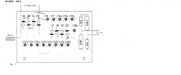
Rather than measuring the Vac delivered by the transformer, you might try measuring the voltage applied to the multiplier network; should be in the 500Vac range. It is not unheard of that one of the Voltage Dependent Resistors (VDR1 or VDR2) shifts parameters over time causing low voltage.
Attachments
Rather than measuring the Vac delivered by the transformer, you might try measuring the voltage applied to the multiplier network; should be in the 500Vac range. It is not unheard of that one of the Voltage Dependent Resistors (VDR1 or VDR2) shifts parameters over time causing low voltage.
I have already done this, the reading is 495 Vac for both EHT, the good one and the bad one.
Also, I have switched the units on both speakers and the problem remains on the same one, as well as the neon lamp pcb was switched on both eht and seams to be good.
The only thing I could not check was the VDRs as they show both directions discontinuity.
I was thinking it was the VDR's based on your first post. But if you measured the input to the multiplier and the voltages are identical there, then you have an issue with the multiplier.
Look closely at the traces between the components, there could be a crack in a trace. I've seen that before, but it's quite rare (but you could be a lucky one).
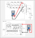
Measure each step of the multiplier and compare, at some point they will differ and that will give you a clue.
Sheldon
Look closely at the traces between the components, there could be a crack in a trace. I've seen that before, but it's quite rare (but you could be a lucky one).
Measure each step of the multiplier and compare, at some point they will differ and that will give you a clue.
Sheldon
If you are getting the same reading downstream of the resistor bridge network, the VDRs are working properly.
A couple questions came to mind:
- Is the speaker with the bad supply audibly or measurably quieter? or is it just that the supply is measuring lower with a HV probe.
- when you are measuring the HV, are you measuring before or after the neon bulb / 10Mohm network?
Besides scrutiny of the board and measurement of each multiplier section as stokessd recommended, you might also consider cleaning both sides of the board with solvent to ensure there isn't any leakage path that had developed to load down the supply.
Thanks Sheldon, I carefully watched the traces after cleaning the surface, nothing was wrong.I was thinking it was the VDR's based on your first post. But if you measured the input to the multiplier and the voltages are identical there, then you have an issue with the multiplier.
Look closely at the traces between the components, there could be a crack in a trace. I've seen that before, but it's quite rare (but you could be a lucky one).
Measure each step of the multiplier and compare, at some point they will differ and that will give you a clue.
Sheldon
Nevertheless, comparing the two modules, I found different voltage readings on the last three diodes, which were lower some 2-300 volts. The problem is, the good one has the original diodes which I can not find the specs and the bad one has the new Vishay diodes (GP 02-40) already replaced by me.
The answerings are:If you are getting the same reading downstream of the resistor bridge network, the VDRs are working properly.
A couple questions came to mind:
- Is the speaker with the bad supply audibly or measurably quieter? or is it just that the supply is measuring lower with a HV probe.
- when you are measuring the HV, are you measuring before or after the neon bulb / 10Mohm network?
Besides scrutiny of the board and measurement of each multiplier section as stokessd recommended, you might also consider cleaning both sides of the board with solvent to ensure there isn't any leakage path that had developed to load down the supply.
- The speaker with the bad supply was already performing at a lower level, this give me the idea to check the EHT.
- The measurements was after the 10M resistor. I have measured also before and voltage where little higher but the same difference in both modules.
- Yes, I had cleaned the wax on both sides of the PCBs.
- Home
- Loudspeakers
- Planars & Exotics
- QUAS ESL 63 EHT issue