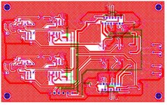
well, one of the youngsters needed some replacement speakers --replacements for the cheap Polks which came with the computer, we settled on a set of Audax's -- as things would have it the project got curiouser and curiouser due to the response curves of the drivers. I chose a pair of LM1876TF's -- dual 20 Watt chips like the LM3875's -- plus active crossover low and high pass filters on one board: Here's a snapshot of the PCB, 50% of real-life size, before I do the photo-engraving and dipping:
Attachments
Sadly I cannot recommend the LM1876. I did several versions with this chip and it sounded nice and the resulting amp can be ridiculously small but the overall sound quality is not comparable to the LM1875 or the LM3875 at all. If you want to make a decent sounding amp you have to choose the latter ones. Ok, for computer speakers it might be enough...
Klaus
Klaus
Reconfigured
The LM1876 has a slightly worse THD figure than the LM3875, slightly better slew rate, somewhat worse (a few dB CMRR etc.)
I reconfigured the circuit -- used SMT resistors and caps, oriented the LM1876F so that it would fit on the heat sink with the PCB perpendicular to it. The power connector is similar to a 0.156" PC connector.
Attachments
First test
Well, I have to stop right now for dinner. Nevertheless, I was quite pleased with the unit -- 0.010 to 0.012% distortion (using HP339 to measure) into an 8R resistive load at 1kHz from 0.6W to 3.0W out.
Well, I have to stop right now for dinner. Nevertheless, I was quite pleased with the unit -- 0.010 to 0.012% distortion (using HP339 to measure) into an 8R resistive load at 1kHz from 0.6W to 3.0W out.
In this case I just used jumpers
it might not look that nice, but the green upper layer traces are jumpers in this case. It takes a little more patience for me to do a board with two sides than I was willing to muster for this project.
it might not look that nice, but the green upper layer traces are jumpers in this case. It takes a little more patience for me to do a board with two sides than I was willing to muster for this project.
looks like the two thick green traces could route outside- one top and one bottom - if that makes sense
thick green
you're right.
For clarity I omitted the ground plane on that shot. One of the green traces can also be eliminated.
More to follow.
you're right.
For clarity I omitted the ground plane on that shot. One of the green traces can also be eliminated.
More to follow.
some more testing
i ran a quick thd vs frequency test -- here's something perplexing -- the thd seems to go up pretty sharply below 250 Hz, but from 300Hz up to 10kHz is 0.009% to 0.012%. A little paradoxical I think.
i ran a quick thd vs frequency test -- here's something perplexing -- the thd seems to go up pretty sharply below 250 Hz, but from 300Hz up to 10kHz is 0.009% to 0.012%. A little paradoxical I think.
i have the filters on
I mean the filters in the HP339a, the waveform itself looks fine, the supply which I am using is very low ripple (microvolts) and the setup is not conducive to ripple.
will check.
jack
I mean the filters in the HP339a, the waveform itself looks fine, the supply which I am using is very low ripple (microvolts) and the setup is not conducive to ripple.
will check.
jack
ok, stupid me
I forgot to "unclick" the 400Hz filter -- with the filter out the THD is much more like the rest of the spectrum, and this isn't bad at all.
I forgot to "unclick" the 400Hz filter -- with the filter out the THD is much more like the rest of the spectrum, and this isn't bad at all.
- Status
- Not open for further replies.
- Home
- Amplifiers
- Chip Amps
- Quadruple Gainclone - yikes !