Hi all,
I downloaded Charles R. Couch's book Designing Vacuum Tube Amplifiers and Related Topics and found that it's a wonderful resource. The only thing that I can't find in there is notes on how to design a quad push-pull output section.
I have a large selection of 50C5 tubes and I think I can get 9, maybe 10, watts out of a dual tube output section, but I would love to get more. I suppose I could just design a guitar amp with some less expensive and more powerful tubes, but I set my personal challenge to what tubes I have on hand at the moment and see how that turns out.
If anyone can point me in a direction, that would be great.
Thanks in advance,
Elain
Take a look at schematics for the Marantz 9, Dynaco MkVI, Berning EA2101 for starters. It's a pretty simple thing to do, but you'll want to verify how the doubled input capacitance of the output stage will affect the amp's open-loop response.
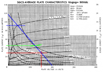
50C5s work pretty good with some slight spec busting, and getting the screen voltage down (the spec sheet actually gives two sets of plate characteristics, one for Vsgsg= 110Vdc and for Vsgsg= 90Vdc). For this loadline (attached) you have an Rl= 1K7 per phase. If you wanted to parallel finals for more output, the voltage would stay the same, and the current would double. That means you would then need: Rl= 1700 / 2= 850R per phase. Your OPT would then need to match your speaker load to: 850 X 2= 1700R (P-2-P for Class A operation, as per the loadline). 50C5s were designed for Class A operation, and should sound quite good with a decent OPT (very rare indeed, considering what 50C5s were almost universally used for back in "the day") a regulated screen supply, fixed bias and some NFB. Being that it's a good Class A VT, you could make the PP final a differential with active tail loading so that it does double duty as a phase splitter.
Four 50C5s (two in parallel per phase) should get you about 10W of output.
Four 50C5s (two in parallel per phase) should get you about 10W of output.
Attachments
Ok, I've run into a snag while doing calculations... When calculating the plate voltage and Imax, I keep getting plate voltages that are way over the maximum values for the 50C5 tube.
According to the book, the equation that I need to use is: Imax x Eb = 3.125 x Pout
Pout being what the desired wattage of the amplifier... in this case, I'm going with 6.5 watts (3.25 per tube, well within the max 5.5 watt limit). I get a value of 20.31 and when looking up Imax on the graph I find 132 mA plug all that into the equation:
20.31 / .132 = Eb and I get a plate voltage of about 153 volts. The max voltage for the plate on the 50C5 is 135 volts. Am I missing something important?
Elain
Ok, I've run into a snag while doing calculations... When calculating the plate voltage and Imax, I keep getting plate voltages that are way over the maximum values for the 50C5 tube.
You don't do calculations when it comes to hollow state design. That only works for solid state. To design VT circuits, use plate characteristics and loadlines.
A Q-Point of 29mA @ 150Vdc gives a reasonable Pd= 4.35W of static plate dissipation. That makes Vgk= -8.0Vdc, and since the 50C5 hasn't cutoff at Vgk= -16V, it's operating in Class A. So draw a Class A loadline from the Q-Point to the Vgk= 0V line to make sure the loadline lies within the saturation region. That intersects at Ip= 92mA, and since Ip= 2.0mA @ Vgk= -16V, the total current is 90mA (since the primary of a PP OPT responds to differential current only). This gives:
I= 90mAp
I= 90E-3 / sqrt(2)= 63.64mArms
Po= (63.64E-3)^2 X 1700= 6.89W
The OPT needs to match the speaker load to: 3K4 (plate-to-plate) to stay within the conditions the loadline prescribes.
"I get a plate voltage of about 153 volts. The max voltage for the plate on the 50C5 is 135 volts. Am I missing something important?"
One thing: VTs are a good deal more "forgiving" than solid state. Busting that spec by a mere 15V isn't going to cause any problems at all. (If anything it might ferret out marginal, gassy 50C5s.) Look at what George (TubeLab) is doing: going just 15V beyond a plate voltage rating is nothing. It allows you to hit a more linear portion of the characteristics, and that's all for the better, sonic-wise.
Thanks Miles. I normally work with ICs and have "thou shalt not supply with greater than spec V+" ingrained in my head. Hopefully this will break me of that.
With the low B+ volts, for bog simplicity I'm tempted to use a split load phasesplitter using parallelled sections of an ECC88 for even low output Z. The input cap of the 50C5 is close enough to an EL84 (12pF); and the ECC88 can easily deal with this.
Prospecting ? To do a 3X3 (triple parallelled p-p) to give 12W with a o/p tranny 1K A-A perhaps an option for UL 40% taps. It should give excellent Quality. Using 250V rated electrolytic caps in the PSU is a real attraction for this project.
richy
Prospecting ? To do a 3X3 (triple parallelled p-p) to give 12W with a o/p tranny 1K A-A perhaps an option for UL 40% taps. It should give excellent Quality. Using 250V rated electrolytic caps in the PSU is a real attraction for this project.
richy
So, after some poking around, I think that I'm understanding that a 4-tube Push-Pull output section is two tube pairs in parallel between the phase splitter and the output transformer. And the transformer has to be able to handle the doubled current and wattage.
Feel free to correct me if I'm wrong.
Feel free to correct me if I'm wrong.
Yes. When paralleling tubes multiply all currents in datasheet (including on graphs) by the number of paralleled tubes. As if you have a N-times fatter tube. Actually, some TV horizontal sweep pentodes contained 2 in parallel inside of one bulb.
http://www.triodeel.com/6ch6amp1.gif as an example. Obviously with the lower B+, the previous stages will have to be reworked.
Thanks Tom. The "Spunky" has the sort of output stage I'm looking for. Though I'm not so sure about the heaters being powered straight from the wall.
I'm going to have to start a new thread for the complete amp since I'm moving out of the output stage now...
fun times.
I'm going to have to start a new thread for the complete amp since I'm moving out of the output stage now...
fun times.
- Status
- Not open for further replies.
- Home
- Amplifiers
- Tubes / Valves
- quad output tube help