Thank you. I could go further. The claimed solution of adding 33pF as Cag at both V1 and V2 makes no sense whatsoever. The LPF is already formed at V1, so why add a second pole at V2? That is only going to affect the inverted signal?
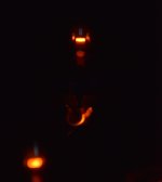
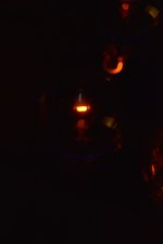
I installed those K40-9y and the voltage on the grids is down to 250mV and the red plating is gone but I still have some blue glow coming from inside the plates on all 4 tubes.
Blue glow is good. Usually when some of the electrons miss the plate and hit the glass. You may see shadows where the plates are. If the plates are not glowing red things are fine.
I've been told the opposite concerning the glow inside the plates, along a straight vertical line on both sides. I know the glow on the glass is ok and quite nice to look at !!
Photo would be lovely to see. Maybe they did a run of mercury rectifiers before your KT66's.
Umm quite a lot on the WEB on KT66 glowing blue - maybe it their thing.
Umm quite a lot on the WEB on KT66 glowing blue - maybe it their thing.
Last edited:
Some blueish glow right at the inside of the anode plates is ok with power tubes. If the glow fills the space between the electrodes completely, the tube is gassy and needs to be discarded.
Best regards!
Best regards!
Another type of glow you may see in power tubes appears on the inside surface of the plate structure. The pattern of the glow will aften appear in strips that vary along with the signal applied to the tube. (i.e., the music.) This type of glow is generally normal as well. It is often caused by a thin layer of atoms that have boiled off the cathode and deposited on the surface of the plate. What you see is the slight flourescence of this material when it is hit by electrons from the cathode. The stripes correspond with the alignment of the grid wires. The varying widths of the stripes demonstrate the operation of the tube. The grid allows restricts the size of the electron beam according to the grid's voltage.
I will try to take a picture tonight but it's hard to find a spot where it's actually visible and the colours on my phone won't be great. from what I can see from the structure of the kt66 it seems to along the vertical support/guide wire for the screen grid.
The extra capacitance to ground is claimed to have been designed into the circuit, but I've never seen any actual evidence for that, or that it was even there when the original couplimg capacitors were new. The amplifier works perfectly well without it. The KT66s already have Cag of about 30pF, and that is the only pole required for stability.
The evidence is in an official Quad service sheet which mentions adding 33pF between each ef86 anode to ground. They also add a similar value cap on the current reissue Quad IIs, though fitted between pins on the KT66 bases to ground.
Well it's bizarre. Apart from being redundant, adding the capacitance to both EF8s means that the bottom half of the amplifier gets slugged twice, thus causing 2HD at the higher frequencies.
Can you post the service sheet?
Can you post the service sheet?
- Home
- Amplifiers
- Tubes / Valves
- Quad II questions

