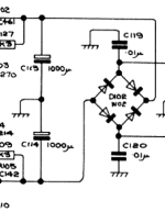
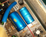
On the FM3 schematic you can see two 1000µF capacitors, C113 and C114 :

But on the board there is one 1000 and one 680µF capacitors. My tuner has never been serviced, and I have seen the same configuration on others units.

Is there a reason for this ?
Should the capacitors be replaced as on the paper or as on the board ?

But on the board there is one 1000 and one 680µF capacitors. My tuner has never been serviced, and I have seen the same configuration on others units.

Is there a reason for this ?
Should the capacitors be replaced as on the paper or as on the board ?
Could it be to allow the rails to rise/fall at slightly different rates to minimise any possible switch on/off noises?
Don't know; my FM3 had both C113 and C114 as 1000 µF.
On/Off noise always comes from my amp (405).
On/Off noise always comes from my amp (405).
If anything it is to make one regulator start before the other, which is also what the PTC resistor across the negative regulator is for, but I suspect it was really just a stock matter. When renovating I always use 2x1000uF and I never hear any startup noises.
The positive rail powers the audio, the negative rail powers the RF and IF.
The positive rail powers the audio, the negative rail powers the RF and IF.