I layed out replacement PCBs for the Quad ESL-63 electrostatic speakers. These are the latest design that was used in the last production runs of the speaker and also are used in all subsequent modern quad electrostatic speakers up to this day (988,989,2805,2905,2812,2912).
I had 50 of each of the boards made for my own use, but I'm willing to share. I'd like to sell only the blank unpopulated boards, but if you can provide a suitable heartstring tugging story of why I should be soldering parts on your boards for you, try me and I just might do it for a fee.
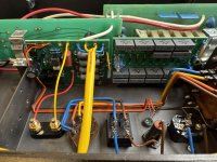
There are three boards in an ESL-63:
If you'd rather buy them elsewhere, I also put the design up on OSHPark for you to buy directly:
Input/Clamp Board
Zener Clamp Board
High Voltage Board
Here's the BOMs


The schematics are attached.
Sheldon


I had 50 of each of the boards made for my own use, but I'm willing to share. I'd like to sell only the blank unpopulated boards, but if you can provide a suitable heartstring tugging story of why I should be soldering parts on your boards for you, try me and I just might do it for a fee.
There are three boards in an ESL-63:
- Input/Clamp Board: Has the input ballast resistors as well as an antenna and RF clamp circuit. In my board I have provisions on the back to mount the input cap and resistor for the audio signal as well as a healthy sized film bypass cap.
- Zener Clamp Board: This clamps a signal large enough to damage the panels. It's a weird triple stacked diode bridge arrangement with zeners across the bridge. It's weird, and I cloned the weirdness. Works well though.
- High Voltage Board: This is a Cockroft/Walton voltage multiplier. It includes the MOV based regulator at the input and the neon isolator at the output. Mine is a clone of the current circuit but I used film caps instead of ceramics.
If you'd rather buy them elsewhere, I also put the design up on OSHPark for you to buy directly:
Input/Clamp Board
Zener Clamp Board
High Voltage Board
Here's the BOMs
The schematics are attached.
Sheldon
Attachments
Last edited:

Actually there are a few items missing to complete the design. My BOM's are never complete it seems
On the Input/clamp board:
On the Zener Clamp Board:
Sheldon
On the Input/clamp board:
- I socketed the 555 timer using one of these: 123-AR08-HZL-TT-ND. That allows the RF clamp to be defeated just by pulling the 555.
- I also added a heat sink to the Triac: HS107-ND
- The triac and the heat sink are held to the PCB with a 4-40 nut and screw
On the Zener Clamp Board:
- I used nylon standoffs to hold the board. This is exactly what quad did but I'm using an insulating standoff: 36-25535-ND
- And I also used a nylon fastener to hold the PCB to the standoff: 145-50M040070G012-ND
- I used 10KV test lead wire for the zener board hookup: 501-1282-ND
Sheldon