I am planning to build this amp -
EL84SE QUAD
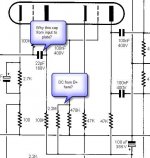
I had a couple of questions regarding the schematic that I have marked in the pic. I dont recall seeing these in other designs and wondered why they were there. Or could they be errors? (I have built other tube amps from schematics before, but I am by no means expert enough to understand the nuances of tube designs like others here)
Also has anyone else built this? What are your thoughts about this design and how it might perform? I saw a positive reference to it on this site - tubebuilder.com
Thanks
UV
EL84SE QUAD
I had a couple of questions regarding the schematic that I have marked in the pic. I dont recall seeing these in other designs and wondered why they were there. Or could they be errors? (I have built other tube amps from schematics before, but I am by no means expert enough to understand the nuances of tube designs like others here)
Also has anyone else built this? What are your thoughts about this design and how it might perform? I saw a positive reference to it on this site - tubebuilder.com
Thanks
UV
Attachments
uvellani,
The 22pF capacitor is a feedback capacitor. It reduces the input stage gain at high frequencies ensuring stabilty. It also has the effect of reducing output impedance of that first stage at high frequencies making sure that the next stage is driven well and that the HF roll off (pole) associated with the input to the second half of the 12AX7 is pushed higher (this is called "pole splitting" since the pole in the first stage is pulled lower by the 22pF feedback cap and the pole into the second stage is pushed higher by the reduced output impedance of the first stage, that is the 2 poles[high frequency corners] are split apart). Its intended to make absolutely sure that dominant pole in the entire feedback loop of the amp is definitely in that first stage and is in fact set by that 22pF capacitor.
The voltage at that point you marked will be set by the 2M2 and 470K voltage divider and will be at about +37V from 0V. The rail feeding that point will be at arounsd +210V so voltage from B+ will be about +180V - that is approx 40V across the 470K and approx 180 across the 2M2 give or take a few volts.
Hope this is some help,
Cheers,
Ian
Thanks gingertube for the detailed explanation.
Would you have any thoughts to offer on the design itself?
Thanks
UV
Would you have any thoughts to offer on the design itself?
Thanks
UV
Design looks like it was done by someone who knew what he was doing. All operating points are fairly conservative. You should get about 8W out of it ( a "poor man's" 300B SET) with around 5% (or even a little more) Harmonic Distortion at full power.
As "fine detail stuff" I might be tempted to use a separate 150R cathode resistor and 220 or 470uF bypass cap on each EL84. Also I might be tempted to add a 100R 2W between the screen and anode (to ensure stability) rather than tie the screen direct to the anode.
The 470K grid resistor per EL84 pair is at the top end of what is required and so don't be tempted to push the EL84s passed about 10.5 Watts dissipation per tube. So stick to 82R per pair in the cathode or 150R or even 160R if you use individual cathode resistors.
Cheers,
Ian
Thanks.
An reasonably priced SE with more power is indeed what I am looking for. So I can try less efficient speakers.
Thanks
UV
You should get about 8W out of it ( a "poor man's" 300B SET)
An reasonably priced SE with more power is indeed what I am looking for. So I can try less efficient speakers.
Thanks
UV
- Status
- Not open for further replies.