The Opamp of my Quad 405 starts clipping when I turn up the volume to a normal listening level . A drop of the suply voltage is measurable with my cheap multimeter. 
So I already figured out what the problem is, I just don't know the solution. Maybe someone is kind enough to help me out with this one.
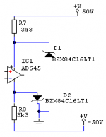
Attached is the schematic of the PSU of the Quad.
 Main PSU capacitors are replaced by some 10000uF/105V units.
When I raise the voltage of the PSU (by selecting a 220V input) the problem becomes less audible.
The supply voltage of the opamp swings around the +- 16.8 V
I think i need to change the value of the resistor and the value of the zener. Maybe someone can help me out with the correct values, or tell me how to calculate them. Or maybe someone has seen this problem before and knows a different solution.
Regards
So I already figured out what the problem is, I just don't know the solution. Maybe someone is kind enough to help me out with this one.
Attached is the schematic of the PSU of the Quad.
Main PSU capacitors are replaced by some 10000uF/105V units.When I raise the voltage of the PSU (by selecting a 220V input) the problem becomes less audible.
The supply voltage of the opamp swings around the +- 16.8 V
I think i need to change the value of the resistor and the value of the zener. Maybe someone can help me out with the correct values, or tell me how to calculate them. Or maybe someone has seen this problem before and knows a different solution.
Regards
Attachments
Assuming that your AD-something op amp draws substantially more current than the original LM301/TL071, it may be a good idea to replace the zeners with simple emitter follower series regulators, as advocated by Bernd Ludwig on several web sites. See, for example, the modifications part of http://www.audiocircuit.com/9121-solidsamplifier-circuit/Commercial/Quad-QUA/9121CMQUA.htm.
Sorry for the mistake, it's an OPA134 that I placed there.
I would like to avoid to place the voltage regulators, which were proposed by Bernd Ludwig.
Mvg,
I would like to avoid to place the voltage regulators, which were proposed by Bernd Ludwig.
Mvg,
LaZarus said:Sorry for the mistake, it's an OPA134 that I placed there.
I would like to avoid to place the voltage regulators, which were proposed by Bernd Ludwig.
Mvg,
In this case You can reduce the 3k3 resistors to 2k2. Than test Your amp. If the clipping still exist, go to 1k8, than test...... But all the time check the temperature of the zeners, or change them to 1.3W type (I don't know BZX84C)
Sajti
There is something funny going on. The OPA134's quiescent supply current is specified as 5mA maximum, which should be low enough when there is
(50V-16V)/3.3kohm=10.303030...mA flowing through the resistors. I'd only expect the switch on and switch off bumps to be worse than with the original op-amp; for this reason, I'd recommend using 1.5kohm, 1W resistors and 15V, 1.3W zeners.
Does the distortion get less when you add decoupling capacitors (10nF to 100nF) between the op amp's power supply pins and ground (in parallel with the zeners, but placed close to the op-amp)? Maybe the impedance of the zeners is too high for an OPA134, causing instability.
Did you perhaps substantially reduce the values of the feedback resistors of the op-amp? That might explain the increased supply current with signal. Did you remember to remove the compensation capacitor for the LM301A? I've no idea what that capacitor would do to an OPA134, but probably nothing good.
One other thing, are you sure that one pin of each zener is grounded, like you've drawn in your schematic? Because of the funny output signal level limiting scheme, that is not the case in the original QUAD405. The QUAD405-2 does have one side of each zener grounded.
mmmk get ready to laugh.......
What's a Zener?
What's an OPamp do?
And what are PSU caps? I've never heard the term before.....
Jeff
What's a Zener?
What's an OPamp do?
And what are PSU caps? I've never heard the term before.....
Jeff
- Status
- Not open for further replies.
- Home
- Amplifiers
- Solid State
- Quad Clipping