hello,
this is the followup of "QUAD 405 revisited (AD844 & vertical MOSFETs)". The AD844, considered as discontinued, is now replaced by a TL071.
A lot of attention got paid for correctly simulating the TL071 using discretes. There is a separate thread about this particular, interesting job.
With the idea of a AD844-based QUAD 405, one had the hope that the AD844 could handle delicate audio mixing with the the crossover correction pulses.
Now, with the idea of a TL071-based QUAD 405, one should not hope that a TL071 can handle delicate audio mixing with the the crossover correction pulses. A TL071 is very slow compared to a AD844.
This new QUAD 405 design clearly acknowledges the inherent weaknesses of the TL071 and all audio grade opamps in general. The beauty of this new design is that any audio opamp can be used. There are no special requirements. Your favorite audio opamp should substitute smoothly.
There are no unobtainable parts, nor expensive, special parts in this new design.
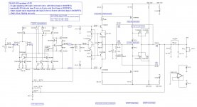
- the QUAD 405 arrangement, relying on a tight & fast inner feedback loop, provides a x5 linearized output buffer capable of outputting 80Vpp on a 2 Ohm load with minimal distorsion.
- the TL071 arrangement is thus relieved from correcting most the crossover distorsion (that's the beauty of this design)
- the QUAD 405 bridge, as usual, needs a 80mA audio drive for swinging +40V / -40V the output (thanks to the 500 ohm feedback resistor in the bridge), and this relatively high current requirement explains why there is a current buffer added at the output of the TL071. This current buffer may be simple, being embedded in the feedback.
- the TL071 arrangement adds a moderate x8 gain to provide the x40 overall gain, which means that with a GBW of only 3Mhz (this is the TL071 spec), the bandwidth of this signal path is 375 kHz, more than adequate for audio
- the TL071 is wired as the outer feedback loop providing the overall x40 gain, which means that the totality of the open-loop gain of the TL071 is used for increasing the precision of the amplification.
The simulation results are excellent.
THD is very low.
In fact, THD is so low that I have generated v0.60 using a 20mA bias current in the driver, and I have generated v.61 trimmed for reduced idle current in the QUAD 405 servo controller and for reduced idle current in the drivers.
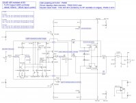
I am attaching the Tina 7 T.I. schematics ready for simulation.
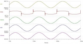
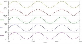
I'm a little bit perplex when viewing the drive signals. The Drive2 signal is asymetric like the two halves (positive swing / negative swing) of the output devices have a different gain. Is there a difference in transconductance between IRF520 and IRF9520 ? Is there a difference in Rds on ? Or is it caused by the difference in forward Beta between the NPN driver and the PNP driver ? I think that THD could be reduced by a factor 2 or 3 if one manages getting the two halves the same transfer function.
Cheers,
Steph
this is the followup of "QUAD 405 revisited (AD844 & vertical MOSFETs)". The AD844, considered as discontinued, is now replaced by a TL071.
A lot of attention got paid for correctly simulating the TL071 using discretes. There is a separate thread about this particular, interesting job.
With the idea of a AD844-based QUAD 405, one had the hope that the AD844 could handle delicate audio mixing with the the crossover correction pulses.
Now, with the idea of a TL071-based QUAD 405, one should not hope that a TL071 can handle delicate audio mixing with the the crossover correction pulses. A TL071 is very slow compared to a AD844.
This new QUAD 405 design clearly acknowledges the inherent weaknesses of the TL071 and all audio grade opamps in general. The beauty of this new design is that any audio opamp can be used. There are no special requirements. Your favorite audio opamp should substitute smoothly.
There are no unobtainable parts, nor expensive, special parts in this new design.
- the QUAD 405 arrangement, relying on a tight & fast inner feedback loop, provides a x5 linearized output buffer capable of outputting 80Vpp on a 2 Ohm load with minimal distorsion.
- the TL071 arrangement is thus relieved from correcting most the crossover distorsion (that's the beauty of this design)
- the QUAD 405 bridge, as usual, needs a 80mA audio drive for swinging +40V / -40V the output (thanks to the 500 ohm feedback resistor in the bridge), and this relatively high current requirement explains why there is a current buffer added at the output of the TL071. This current buffer may be simple, being embedded in the feedback.
- the TL071 arrangement adds a moderate x8 gain to provide the x40 overall gain, which means that with a GBW of only 3Mhz (this is the TL071 spec), the bandwidth of this signal path is 375 kHz, more than adequate for audio
- the TL071 is wired as the outer feedback loop providing the overall x40 gain, which means that the totality of the open-loop gain of the TL071 is used for increasing the precision of the amplification.
The simulation results are excellent.
THD is very low.
In fact, THD is so low that I have generated v0.60 using a 20mA bias current in the driver, and I have generated v.61 trimmed for reduced idle current in the QUAD 405 servo controller and for reduced idle current in the drivers.
I am attaching the Tina 7 T.I. schematics ready for simulation.
I'm a little bit perplex when viewing the drive signals. The Drive2 signal is asymetric like the two halves (positive swing / negative swing) of the output devices have a different gain. Is there a difference in transconductance between IRF520 and IRF9520 ? Is there a difference in Rds on ? Or is it caused by the difference in forward Beta between the NPN driver and the PNP driver ? I think that THD could be reduced by a factor 2 or 3 if one manages getting the two halves the same transfer function.
Cheers,
Steph
Attachments
-
 QUAD 405 REVISITED (NO AD844 ANYMORE) V0.60 - system waveforms at 10mV input.JPG88.7 KB · Views: 1,085
 -
QUAD 405 revisited (no AD844 anymore) v0.60.zip8.3 KB · Views: 224
-
QUAD 405 revisited (no AD844 anymore) v0.61.zip8.3 KB · Views: 173
-
 QUAD 405 REVISITED (NO AD844 ANYMORE) V0.60.JPG275.1 KB · Views: 1,241
 -
 QUAD 405 REVISITED (NO AD844 ANYMORE) V0.60 - system waveforms at 100mV input.JPG91.5 KB · Views: 1,000
 -
 QUAD 405 REVISITED (NO AD844 ANYMORE) V0.60 - system waveforms at 1000mV input.JPG91.8 KB · Views: 833
Last edited:
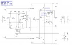
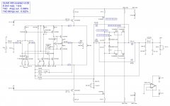
this is v0.70
It differs from v0.60 in the way the TL071 gets wired. This time we are entering the audio signal on the TL071 non-inverting pin, and we apply the global feedback on the inverting pin of the TL071. This is thus more orthodox than v0.60.
The QUAD 405 controller is now used in a non-inverting mode.
Advantages :
- the amplifier now provides a high impedance input, not involved in feedback,
- as a consequence, the amplifier is maybe able to connect on a 50K ohm volume potentiometer (high impedance) seen through a cinch cable (high capacitance) - but I still need to check this. This question is the famous "interface distorsion" from the early eigties. One need to test the frequency response and stability using 9 different source scenario using a 2D matrix of low/medium/high impedance and low/medium/high capacitance. Depending on the volume and balance setting, and depending on the cable lenght, an amplifier may show "dangerosity zones" where stability and/or frequency response get corrupt.
- it is now possible to design a reliable local high-frequency local negative feedback around the TL071.
Disadvantages :
- The QUAD 405 controller doesn't work anymore in the inverting mode; it is now working in non-inverting mode, and this raises distorsion. The QUAD 405 local controller now experiences a common mode voltage swing, making the associated current buffer performing with less precision.
- It is less easy to implement a drive current limiter
To do list :
- Implementing a drive current limiter is mandatory. Without it, put a 1250mV 1 KHz at the input and you will see the amplifier not recovering from the localized overloads. There is a HF oscillatiopn developping in case of overload.
- Fine tune the frequency compensation scheme. The frequency compensation scheme got optimized for a 2 ohm load, but the result is degraded with a 4 ohm load, and the amplifier exhibits HF instability on a 8 ohm load
One may ask why there is a buffer just after the TL071. The reason for this buffer, it to isolate the TL071 from the pulsing current requirement of the drive signal.
Omitting this buffer, and connecting the TL071 output straight to the QUAD 405 controller is very possible. But then, altough the TL071 is delivering a smooth sinusoïdal voltage waveform, the TL071 will be forced to deliver pulsing currents waveforms, during the dead-zone of the Class B crossover.
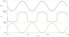
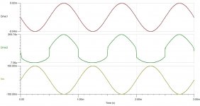
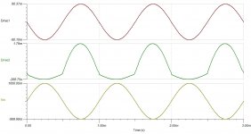
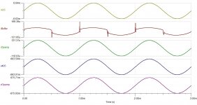
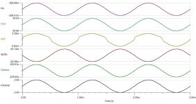
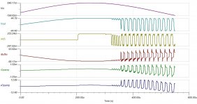
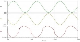
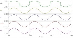
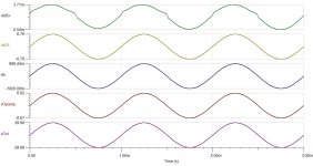
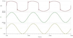
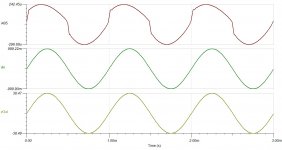
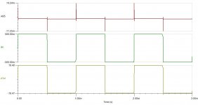
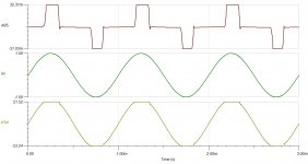
An illustration of this can be found in the v.70 system waveforms at 10mV input, 100mV input and 1000mV input.
The TL071 voltage (see vOpamp trace) is sinusoïdal, the TL071 current is sinusoïdal (see iOpamp trace), but the current that gets injected in the QUAD 405 controller is far from sinusoïdal (see iBuffer trace).
This buffer is thus necessary, if one wants to obey the design idea of relieving the opamp from crossover distorsion elimination. See post #1.
But, practically, I am a bit concerned by the worsening of THD exhibited by v0.70 compared to v0.60, so there is maybe a dog in v0.70, like the buffer not isolating the TL071 correctly (there is a clue about this in the 10mV system waveforms), or the QUAD 405 controller REALLY needing to operate without common-mode for obtaining very low THD in the QUAD 405 bridge, or, the QUAD 405 needing a redesign for better coping with common mode voltage swing .
Question :
- Is there a technique for automatically adjusting the frequency compensation scheme like using a capacitance multiplier somewhere in the circuit, driven by an indirect load impedance measurement circuit ? This seems to be used in certains opamps. So why not into an audio power amplifier in 2010 ? I think the idea got presented in Wireless World long time ago using the "load invariant" vocable.
I'm delivering some attached files, plus a .zip containing everything in one shot, including the schematic ready for simulation under Tina 7 T.I.
Cheers,
Steph
It differs from v0.60 in the way the TL071 gets wired. This time we are entering the audio signal on the TL071 non-inverting pin, and we apply the global feedback on the inverting pin of the TL071. This is thus more orthodox than v0.60.
The QUAD 405 controller is now used in a non-inverting mode.
Advantages :
- the amplifier now provides a high impedance input, not involved in feedback,
- as a consequence, the amplifier is maybe able to connect on a 50K ohm volume potentiometer (high impedance) seen through a cinch cable (high capacitance) - but I still need to check this. This question is the famous "interface distorsion" from the early eigties. One need to test the frequency response and stability using 9 different source scenario using a 2D matrix of low/medium/high impedance and low/medium/high capacitance. Depending on the volume and balance setting, and depending on the cable lenght, an amplifier may show "dangerosity zones" where stability and/or frequency response get corrupt.
- it is now possible to design a reliable local high-frequency local negative feedback around the TL071.
Disadvantages :
- The QUAD 405 controller doesn't work anymore in the inverting mode; it is now working in non-inverting mode, and this raises distorsion. The QUAD 405 local controller now experiences a common mode voltage swing, making the associated current buffer performing with less precision.
- It is less easy to implement a drive current limiter
To do list :
- Implementing a drive current limiter is mandatory. Without it, put a 1250mV 1 KHz at the input and you will see the amplifier not recovering from the localized overloads. There is a HF oscillatiopn developping in case of overload.
- Fine tune the frequency compensation scheme. The frequency compensation scheme got optimized for a 2 ohm load, but the result is degraded with a 4 ohm load, and the amplifier exhibits HF instability on a 8 ohm load
One may ask why there is a buffer just after the TL071. The reason for this buffer, it to isolate the TL071 from the pulsing current requirement of the drive signal.
Omitting this buffer, and connecting the TL071 output straight to the QUAD 405 controller is very possible. But then, altough the TL071 is delivering a smooth sinusoïdal voltage waveform, the TL071 will be forced to deliver pulsing currents waveforms, during the dead-zone of the Class B crossover.
An illustration of this can be found in the v.70 system waveforms at 10mV input, 100mV input and 1000mV input.
The TL071 voltage (see vOpamp trace) is sinusoïdal, the TL071 current is sinusoïdal (see iOpamp trace), but the current that gets injected in the QUAD 405 controller is far from sinusoïdal (see iBuffer trace).
This buffer is thus necessary, if one wants to obey the design idea of relieving the opamp from crossover distorsion elimination. See post #1.
But, practically, I am a bit concerned by the worsening of THD exhibited by v0.70 compared to v0.60, so there is maybe a dog in v0.70, like the buffer not isolating the TL071 correctly (there is a clue about this in the 10mV system waveforms), or the QUAD 405 controller REALLY needing to operate without common-mode for obtaining very low THD in the QUAD 405 bridge, or, the QUAD 405 needing a redesign for better coping with common mode voltage swing .
Question :
- Is there a technique for automatically adjusting the frequency compensation scheme like using a capacitance multiplier somewhere in the circuit, driven by an indirect load impedance measurement circuit ? This seems to be used in certains opamps. So why not into an audio power amplifier in 2010 ? I think the idea got presented in Wireless World long time ago using the "load invariant" vocable.
I'm delivering some attached files, plus a .zip containing everything in one shot, including the schematic ready for simulation under Tina 7 T.I.
Cheers,
Steph
Attachments
-
 QUAD 405 REVISITED V0.70 - system waveforms at 10mV input.JPG118.7 KB · Views: 732
 -
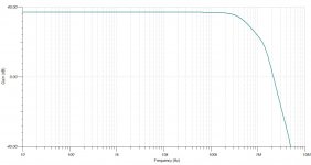
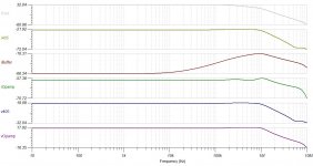 QUAD 405 REVISITED V0.70 - system gains on 2 ohm load.JPG165.9 KB · Views: 180
 -
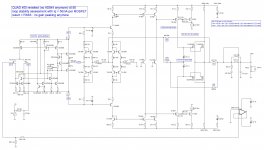
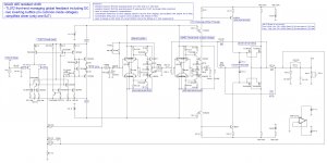
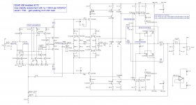 QUAD 405 REVISITED V0.70 - schematic.JPG296.6 KB · Views: 431
 -
 QUAD 405 REVISITED V0.70 - system waveforms at 100mV input.JPG119.5 KB · Views: 279
 -
 QUAD 405 REVISITED V0.70 - system waveforms at 1000mV input.JPG119.8 KB · Views: 116
 -
QUAD 405 revisited v0.70.zip688.1 KB · Views: 141
Last edited:
This may be very interesting for you, as you have interest in Quad 405
YouTube - Csöves single ended VS Quad405
Sound reproduction is a very interesting thing...i have listened, this same video, using three different amplifiers..the speaker was fixed....just one speaker...... and i found my evaluation the same..but the different between these two amplifiers, the Tube one and the Quad 405, were different.... without change my prefered one..but distance between them..how better the best one is...this was different..the scale was different..the evaluation numbers were different.
regards,
Carlos
Last edited:
Nice work. Just curious why you didn't use the TL071 model already provided in TINA-TI? I imagine that being a TI core product that the model would be good.
A nice exercise but - TL071 the 72 and on odd occasions when 4 amps are deemed necessary; the 74...all are the ubiquitous input stages for big power Public address amplifiers - not the refined. You certainly wouldnt find KRELL or Mark Levinson designing much with them as the main input stage. Our workshops have always found the TLO range to be the "Steinway of op-amps" - hard brittle tonal character.
But I've always personally found the FET based input a tad harsh and a bit fizzy at the top end, hence my personal preference for an all BJT inlet... or with bottles.
But I've always personally found the FET based input a tad harsh and a bit fizzy at the top end, hence my personal preference for an all BJT inlet... or with bottles.
this is now v0.80
same idea as v0.70 but a completely different implementation, that can be described as conservative-minded :
- the 80 mA buffer is an inverting op-amp using discretes
- the Q405 controller is a non-inverting op-amp using discretes
- the driver is no more relying on push-pull current mirrors (and no phase inversion)
Could not get it working on simulation in a decent domain enveloppe. The simulator only finds the operating point for a 4 ohm load. The simulator doesn't find the operating points for a 8 ohm load, and for a 2 ohm load.
Have tried to add a simple i405 current limiter, but when adding the components (two resistors and two transistors), the simulator cannot find the operating point anymore.
The simulator doesn't like computing this arrangement, with the TL071 used as global feedback.
If one uses the TL071 as a x2 gain block (the simulator doesn't like the TL071 being wired as unity gain buffer), not involved into the feedback, and sending a small current (less than 2mA) into the inverting input (using capacitive coupling) of the 80mA buffer, one gets a decent revisited QUAD405. A DC-servo arrangement using another TL071 may the help reducing the offset, and may enable a capacitorless design.
I had great expectations with this, but now I have cooled down. There are too many drawbacks. Simulator very often doesn't compute the operating point. Transistor count is high. Quiescent currents in the 80mA buffer and in the Q405 controller are quite high. There is a waste in open-loop gain using this simple driver arrangement, omitting the current mirrors, and shorting the base of the driver with a low value resistor.
The attached .zip contains everything including the schematic ready for simulation using Tina 7 T.I.
Cheers,
Steph
Attachments
-
 QUAD 405 REVISITED V0.80 - gain on 4 ohm load.JPG136.6 KB · Views: 143
 -
 QUAD 405 REVISITED V0.80 - system waveforms at 570mV input.JPG131.6 KB · Views: 114
 -
 QUAD 405 REVISITED V0.80 - schematic.JPG366.2 KB · Views: 260
 -
 QUAD 405 REVISITED V0.80 - system waveforms at sinus clipping (oscillation instead of recover).JPG150 KB · Views: 196
 -
QUAD 405 revisited v0.80.zip521.9 KB · Views: 121
now we enter v0.9x
Based on a few considerations :
1. The idea of using a TL071 both as front-end and global feedback cannot be put in practice. With a TL071 used as global feedback, there is a catastrophic behaviour in case of saturation, being a sinus clipping saturation, or being a transient saturation like the edges of a square wave. The reason of this catastrophic behaviour is easy to understand : the front-end starts toggling between the two supply rails if the rest of the chain cannot deliver the requested output.
2. Maybe the idea of using a TL071 both as front-end and global feedback is possible if the whole amp is managed in such a way that overload can't occur. One may think about an input amplitude limiter. One may think about a dV/dt limiter at the input, in the form of a low-pass filter. It all adds complexity and tradeoffs. I won't deal with this at the moment.
3. This new Q405 controller is built around a TL071 device. This new Q405 controller operates at very low quiescent current, and drives the gate of a vertical MOS driver.
The attached .zip contains everything including some schematics ready for simulation using Tina 7 T.I.
Cheers,
Steph
Attachments
-
QUAD 405 revisited v0.93.zip525.3 KB · Views: 133
-
 QUAD 405 REVISITED V0.93 - schematic.JPG277.3 KB · Views: 299
 -
 QUAD 405 REVISITED V0.93 - system waveforms at 8000mV input.JPG91.9 KB · Views: 218
 -
 QUAD 405 REVISITED V0.93 - gain on 8 ohm load (peaking).JPG136.7 KB · Views: 93
 -
 QUAD 405 REVISITED V0.93 - system waveforms square wave 8 ohm (fail).JPG65.3 KB · Views: 126
Last edited:
In the thread http://www.diyaudio.com/forums/soli...e-simulation-using-discretes.html#post2138458 I am showing that the built-in Tina 7 T.I TL071 model is completely wrong regarding the power supply pins and regarding the output current capability.Nice work. Just curious why you didn't use the TL071 model already provided in TINA-TI? I imagine that being a TI core product that the model would be good.
After those funky experiments, we will now concentrate on more practical, more realistic circuits. The aim now, is to roll out schematics having a decent probability to work in the real world.
The new Q405 controller :
- provides an emitter-follower high-impedance non-inverting input,
- is used in the non-inverting mode,
- v1.00 uses BJTs as drivers for the vertical MOSFETS,
- v2.00 uses MOSFETs as drivers for the vertical MOSFETs,
- v1.10 and v2.10 use a bootstrapped Q405 controller, supposed to reduce distorsion, eliminating the common-mode voltage seen by the controller
The new Q405 controller is wired as a x5 amp, with a tight negative local feedback, locally ironing-out most of the crossover distorsion. Actually, this new Q405 controller may be used as a Lo-Fi amplifier :
v1.00 Q405 controller specs (x5 gain) :
3.809% THD with a small 4Vpp output signal on a 2 ohm load
0.450% THD with a large 80Vpp output signal on a 2 ohm load
v2.00 Q405 controller specs (x5 gain) :
1.338% THD with a small 4Vpp output signal on a 2 ohm load
0.176% THD with a large 80Vpp output signal on a 2 ohm load
If we now put a TL071, both as front-end and as global feedback, we get a significant distorsion reduction.
About the TL071 in such topology :
- it is not involved in the crossover distorsion reduction,
- it delivers a linear voltage and linear current, without any spikes or edges,
- it needs to source less than one milliamp,
- the output voltage swing is approx 8 Volt (fits easy within +15V / -15V rails)
- it defines the voltage offset at the output
- it provides a very high input impedance (input on the TL071 non-inverting pin)
v1.00 revised QUAD 405 specs (32dB gain)
0.057% THD with a small 4Vpp output signal on a 2 ohm load
0.047% THD with a large 80Vpp output signal on a 2 ohm load
v2.00 revised QUAD 405 specs (32 dB gain)
0.054% THD with a small 4Vpp output signal on a 2 ohm load
0.057% THD with a large 80Vpp output signal on a 2 ohm load
After comparing the figures between the TL071-feedbacked amps, and between the bare Q405 controllers, there is one valid conclusion coming : the TL071 is indeed defining the final result, knocking down distorsion to reasonable levels.
The TL071 may be replaced by any other audio opamp (like NE5532, OPA134, ... ) after minimal changes in the local opamp frequency compensation (feedback capacitor and resistor), and in the global frequency compensation (feedback capacitor for forming a global 50 kHz or 100 kHz lowpass).
It would be interesting to build some boards, experience the real-world stability, and listen to various implementations using various audio opamps as front-ends.
The same revisited v1.00 or v2.00 QUAD 405 board may have as features :
- low cost (not as cheap as ChipAMP, but a lot more powerful)
- scalability (put 1, 2, or 4 MOSFETs pairs at the output)
- versatile front-end tonal signature (use the audio opamp of your choice)
- versatile output devices tonal signature (use vertical MOSFETs or lateral MOSFETs)
- a honest approach for dealing with crossover distorsion, without approximations
- in a pure Class B approach (bias the ouput devices below threeshold)
- in a Class AB approach (bias the output devices above threshold)
See attached files. The two .zip contain everything, including Tina 7 T.I. schematics ready for simulation, as usual.
Steph
Attachments
-
 QUAD 405 REVISITED V2.00.JPG254.8 KB · Views: 252
 -
 QUAD 405 REVISITED V2.00 - system waveforms 50mV input.JPG118.7 KB · Views: 163
 -
 QUAD 405 REVISITED V2.00 - system waveforms 1000mV input.JPG120.7 KB · Views: 104
 -
QUAD 405 revisited - controllers v1.00 v1.10 v2.00 v2.10.zip284.1 KB · Views: 121
-
QUAD 405 revisited - amplifiers v1.00 v1.10 v2.00 v2.10.zip760.9 KB · Views: 129
back to simplicity !
In this implementation, the TL071 is completely involved in the crossover distorsion process, providing the high gain and relying on the Q405 feedback bridge.
Is this approach a trivial, ugly approach, destroying any chances of audiophile grade subjective results ?
Anyway, for sure, this circuitry has the advantage of simplicity, with only a few parts on the signal path.
v3.00 is a pure QUAD 405 topology, with 100% of the feedback coming from the Q405 bridge, plus a small global feedback for the ultrasonic frequencies using a small capacitor between the output and the negative input of the opamp.
V3.01 is a mixed QUAD 405 topology, with the Q405 bridge providing 4x times the required gain, and a conventional resistor/resistor attenuator knocking the overall gain down to 32 dB in the whole audio frequency range, and the usual small capacitor for managing the ultrasonic frequencies.
The special feedback arrangement is made in such a way that it doesn't considerably load the opamp. This feature is needed. If the feedback network considerably loads the opamp, the opamp must supply more current, and this translates into an overall gain increase, through the supplies of the opamp.
The results - on simulation - are truly amazing.
The THD figures are more than decent with a 32dB voltage gain, both at low levels (50mV input), and at high level (1000mV input).
The square wave response is fast and clean. This is the result of me having tuned the frequency compensation elements located into the feedback loop.
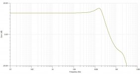
Once the square wave optimization is done, the simulator shows a straight frequency response extending beyond 60 KHz, with a smooth phase shift, only 90 degree at 90 KHz. In such context I have not bothered in refining any further the frequency response. As a cherry on the pie, the sinus clipping recovery occurs smoothly.
One may substitute the TL071 with a more elaborate audio opamp like a OPA134, in which case the frequency compensation elements will need some retuning in the feedback network.
As usual, the attached .zip contains everything including the Tina 7 T.I. schematics ready for simulation.
Cheers,
Steph
In this implementation, the TL071 is completely involved in the crossover distorsion process, providing the high gain and relying on the Q405 feedback bridge.
Is this approach a trivial, ugly approach, destroying any chances of audiophile grade subjective results ?
Anyway, for sure, this circuitry has the advantage of simplicity, with only a few parts on the signal path.
v3.00 is a pure QUAD 405 topology, with 100% of the feedback coming from the Q405 bridge, plus a small global feedback for the ultrasonic frequencies using a small capacitor between the output and the negative input of the opamp.
V3.01 is a mixed QUAD 405 topology, with the Q405 bridge providing 4x times the required gain, and a conventional resistor/resistor attenuator knocking the overall gain down to 32 dB in the whole audio frequency range, and the usual small capacitor for managing the ultrasonic frequencies.
The special feedback arrangement is made in such a way that it doesn't considerably load the opamp. This feature is needed. If the feedback network considerably loads the opamp, the opamp must supply more current, and this translates into an overall gain increase, through the supplies of the opamp.
The results - on simulation - are truly amazing.
The THD figures are more than decent with a 32dB voltage gain, both at low levels (50mV input), and at high level (1000mV input).
The square wave response is fast and clean. This is the result of me having tuned the frequency compensation elements located into the feedback loop.
Once the square wave optimization is done, the simulator shows a straight frequency response extending beyond 60 KHz, with a smooth phase shift, only 90 degree at 90 KHz. In such context I have not bothered in refining any further the frequency response. As a cherry on the pie, the sinus clipping recovery occurs smoothly.
One may substitute the TL071 with a more elaborate audio opamp like a OPA134, in which case the frequency compensation elements will need some retuning in the feedback network.
As usual, the attached .zip contains everything including the Tina 7 T.I. schematics ready for simulation.
Cheers,
Steph
Attachments
-
 QUAD 405 REVISITED V3.01 - schematic.JPG198.5 KB · Views: 428
 -
 QUAD 405 REVISITED V3.01 - system waveforms 50mV input.JPG89 KB · Views: 344
 -
 QUAD 405 REVISITED V3.01 - system waveforms 1000mV input.JPG92.8 KB · Views: 275
 -
 QUAD 405 REVISITED V3.01 - system waveforms 500mV input (square wave).JPG62 KB · Views: 266
 -
 QUAD 405 REVISITED V3.01 - gain & phase.JPG122.2 KB · Views: 324
 -
 QUAD 405 REVISITED V3.00 - schematic.JPG195.6 KB · Views: 270
 -
QUAD 405 revisited v3.00 & v3.01.zip521.3 KB · Views: 126
-
 QUAD 405 REVISITED V3.01 - system waveforms 1500mV input (clipping).JPG85.5 KB · Views: 180
hello,
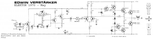
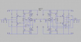
here is another Quad 405 revisited. It is based on LTspiceIV instead of Tina 7 T.I. Note how the TL071 now shows as a subcircuit. Actually, I designed this Quad 405-revisited as an Edwin amp follow-up. Who knows, that's maybe how P.J. Walker and M.P. Albinson developed the Quad 405, without telling us. The attached .zip contains everything, but you'll need LTspiceIV (free download on Linear Technology website) for enjoying it.
Cheers,
Steph
Attachments
- Status
- Not open for further replies.
- Home
- Amplifiers
- Solid State
- QUAD 405 revisited (TL071 & vertical MOSFETs)