Hi ppl
i have built myself a Quad 405-2 clone. It is very close to working now but there is a problem i do not know how to fix.
The output has a parisitic oscillation on positive cycles ( both channels).
It's frequency is about 4Mhz and it is small but visible on my scope.
It also seems to cause crossover distortion when it's present 🙁.
I have managed to get rid of it by whacking a 50 ohm resistor at the base of TR9 ( positive dumper) and the crossover distortion becomes much less (how much is acceptable??).
I think this is a dirty way of getting rid of it though.
Here is a link to the schematic:
http://home.jps.net/~shiloh/
These are the changes i have made to the circuit:
TR9 and TR10 are MJ21194's
TR7 and TR8 are BD244C's
TR1 is a 2N5401
TR2 is a 2N5550
TR3 is a ZTX753
If anyone knows what i can do to get rid of it i would be grateful.
Thanks a lot
Craig
let's solder a 2,2n/200V folie cap between the base and emmiter of the "lower" output transistor (TR10 on the schema)
the Quad405 likes oscillate, kill the speaker, etc... that a real sh*t amp, sorry...
the Quad405 likes oscillate, kill the speaker, etc... that a real sh*t amp, sorry...
Thanks for the reply edl.
Why do you think the Quad 405-2 is a poor amplifier?
Could you expand on why this capacitor is needed and how you obtained its value, i am a bit nervous connecting the base to the negative rail?
I have got all distortion to disappear by using a 70 ohm load, what does this suggest as to its source?
Cheers
Craig
I have built several 405 clones in the past and used a copy of the Quad PCB layout. I had no problems with oscillation even using 2N5038 output transistors which are very fast with an Ft of 60Mhz. Perhaps you have a problem with PCB layout. You can disconnect the output transistors and run the amplifier into a resistor of about 5k to check the performance of the class A stage. When working properly these amps are capable of very low distortion ( We measured 0.0018% ). I think these amplifiers are much maligned. Operated within their design parameters (i.e. not trying to drive 8 ohm loudspeakers which measure 3 ohms) they perform very well. The 405-2 has a much more sophisticated current limit circuit and addresses many of the problems of the earlier 405. The amplifier is also unconditionally stable and will happily drive an 8uF motor start capacitor as a load. The current dumping principal is a very elegant solution to the design of a high power amplifier and I am sure can be developed further. I shall have a look when I get home and see if I can be of more assistance
Stuart
Stuart
Craig,
First make shure that you don't have any ground loops.
Please also use bulk cables to connect each 405 module to common ground point.
If still oscilate, add a 100pF between base and collector of Tr8 (BD244C).
Regards, Tibi
First make shure that you don't have any ground loops.
Please also use bulk cables to connect each 405 module to common ground point.
If still oscilate, add a 100pF between base and collector of Tr8 (BD244C).
Regards, Tibi
Tvicol, thanks for you help.
My grounds are ok i think i have used thick wire from each module to a big star ground and my grounding scheme on the modules is as Quad specified in their circuit, the 10 ohm resistor seperates the lower current parts of the circuit from the drivers and dumpers ground.
I will try the 100pf cap later today when i get time i hope it works i am desperate to listen to some music!!
Hi 405man,
any help you could offer into this annoying problem is very welcome 🙂.
I think my PCB layout is ok i have avoided parallel tracks and things are quite spaceous, also a big physical gap from the drivers to the op amp.
Any ideas as to what is causing crossover distortion although it is quite small it is visible?
Thanks
Craig
On some early 405s there is a 1nF capacitor between base and collector of Tr10however if you have visible crossove distortion then I think you have a more serious problem. I would check around the bridge components, when working properly you will not be able to see any distortion.
Stuart
Stuart
Hi
I have tried the 100pf capacitor but it didnt get rid of my oscillation, i think this is because the oscillation is only over the positive cycle.
If take away the signal source i can actually see the oscillation on the offset voltage with my scope set very sensitive, could this mean it is oscillating due to RF inteference?
I have checked my bridge and everything is correct but i can still see crossover distortion, what could be causing this if the bridge is working?
I thought it might be the output transistors i am using being Darlington and needing 1.2V to conduct and leaving the output under class A control too long. But other people have used these transistors in the same circuit without problems.
on the good side of things this amp delivers 112 watts RMS into 8 ohms before clipping 🙂
Cheers
Craig
I forgot to mention that crossover distoriton only becomes visible at high frequencies about 10Khz but is visible even at low output levels like a few watts.
Same with the oscillation, it is less visible at lower test frequencies.
Cheers
Craig
Same with the oscillation, it is less visible at lower test frequencies.
Cheers
Craig
I would try a pair of non-darlington output transistors first or add extra diodes between the bases so that the output pair only require 0.6V bias as in the 405-2. I can send you a pair from a 405-2 if you dont have any handy
Stuart
Stuart
Thanks very much for the kind offer, but i have 12 Toshiba 2SD424 transistors, i decided not to use them though.
I will try and correct the biasing with my existing MJ21194's as they cost me about 3 pounds each and i bought 8!
I hope i understand this correctly as i am still learning electronics. But would adding diodes make the voltage required to turn on the dumpers higher?
If so i would need to short the diode D6 between the bases of TR9 and TR10 and short either D5 or D13 between TR7's collector and TR9's base in order to make the voltage lower to compensate for the darlington pair.
Please correct me if i'm wrong ( i think i may be)
Cheers
Craig
The diode D6 connected between the bases of TR8 and TR9 according to the 405 manual. Without the diode the output of the class A amplifier has to swing +- 0.6V before the output transistors conduct and this was the case in the early 405s. D6 was added to reduce this to +-0.3V. ( If you replace D6 with 2 diodes in the standard circuit then the output stage would be permanently biased but with no control of the bias current the amplifier would quickly be destroyed by thermal runaway )
If you have replaced TR9 and TR10 with darlingtons then there are 2 junctions to forward bias in TR9 and 1 in TR8 this will cause asymmetry in the operation of the output stage and you will now need 2 diodes in place of D6 but the output stage will still be asymmetrical because you have a darlington in place of TR10. I think the first thing to do would to replace the output transistors and a single diode for D6 and see how that works
I would have a look at the article by Bernd Ludwig at the link below for a description of how the 405 works.ernd Ludwig
http://www.dc-daylight.ltd.uk/Valve-Audio-Interest/QUAD/QUAD-405-Modification/405_Qw_6.pdf
Stuart
405man i think i follow you now,
so i will need to put in extra diodes where i thought i had to remove them.
One before TR9's base and one between TR9 and Tr8 bases to increase the idle voltage.
MJ21194 is darlington isn't it, it isnt actually written anywhere?
in the data sheet it says
Vbe (On) = 2.2V at
Ic 8A and
VCE 5V DC
Thanks for the advice
Craig
hoping not
hoping you didn't make such errors easy to neglect as below
1, the quality of your power supply;
2,whether L2/C8=R38*(R20//R21).
enjoy
hoping you didn't make such errors easy to neglect as below
1, the quality of your power supply;
2,whether L2/C8=R38*(R20//R21).
enjoy
by the way ,
I've always considered that the common ground which was round without any doubt should be the smaller ,the better.
of course, that refer to a moderate extension.
I've always considered that the common ground which was round without any doubt should be the smaller ,the better.
of course, that refer to a moderate extension.
Ary thanks for suggestions, my power supply is quite good, plenty of capacitance plus the 100nf accross each rail.
However using your equation he bridge doesn't balance with my amplifier where R20 and R21 = 500 ohm in //, R38 = 47ohm, C8 and L2 = 120pf and 3.3uH.
This doesn't equal unity and neither does it in Quads design using 3uH.
To balance my bridge i would have to make R20//R21 = 585 ohm?
Cheers
Craig
However using your equation he bridge doesn't balance with my amplifier where R20 and R21 = 500 ohm in //, R38 = 47ohm, C8 and L2 = 120pf and 3.3uH.
This doesn't equal unity and neither does it in Quads design using 3uH.
To balance my bridge i would have to make R20//R21 = 585 ohm?
Cheers
Craig
yes
That's the key theory of this circuit.
according to the current dumping, this equation must be achieved as you must have known.
so try to accomplish it ,
by the way,changing R20//R21 is very easy and safely,so just do it.
hoping that works.
and if your common ground is a very large area, may be you should make it smaller.
after the all, it may still have loop part circuit when some heavy part(connecting to the common ground) changes suddenly.
enjoy
yes no issues changing R20//R21, they control the gain of the circuit aswell as being part of the error voltage cancelling bridge.
so increasing the value will marginally increase the gain.
I actually tested this circuit without these resistors at all by accident with no ill effect apart from very high gain 🙂 .
RE theory and schematics:
I have lots of Quad stuff i can send you, i can send you 2 very good articles from wireless world covering lots of current dumping theory aswell as a high-res schematic.
Cheers
Craig
Thank you
If the bridge was exactly accomplished, then I have no further idea. 🙁
And thank you for your help
My Email:xuwei00@163.com.
If the bridge was exactly accomplished, then I have no further idea. 🙁
And thank you for your help
My Email:xuwei00@163.com.
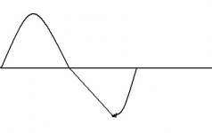
I have gotten rid of my parasitic oscillation by putting a 330pf cap between base and collector of TR7 plus a 100ohm resistor in series with its base.
🙂
however..... 😀
when rolling up the input level towards the max output level of 100W my negative cycle now does this, almost like its trying to become a triangle wave?
I believe this is tied in with the crossover distortion i can see.
Any ideas?
🙂
however..... 😀
when rolling up the input level towards the max output level of 100W my negative cycle now does this, almost like its trying to become a triangle wave?
I believe this is tied in with the crossover distortion i can see.
Any ideas?
Attachments
- Status
- Not open for further replies.
- Home
- Amplifiers
- Solid State
- Quad 405 Parasitic Osacillation!