I am applying Dada mods to my Quad 405 MK-1. My boards are M12368 Issue 10.
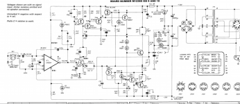
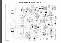
Please see attached pictures of Schematic and board lay out from service manual.
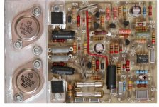
Now compare it to Picture of board by DADA , specifically orientation of C2.
Which one is correct?
I have looked at different websites, like Keith Snook, deSmith etc and everyone advises to change the capacitor but no one advises to reverse the polarity?
Many Thanks in advance for your guidance.
Please see attached pictures of Schematic and board lay out from service manual.
Now compare it to Picture of board by DADA , specifically orientation of C2.
Which one is correct?
I have looked at different websites, like Keith Snook, deSmith etc and everyone advises to change the capacitor but no one advises to reverse the polarity?
Many Thanks in advance for your guidance.
Attachments
Reverse the polarity of a non-polarised film capacitor ?
Its not my favourite type of capacitor -stacked film but some like it .
I would be using a polypropylene version.
Is it C4 or C2 we are talking about ? You mention both .
Its not my favourite type of capacitor -stacked film but some like it .
I would be using a polypropylene version.
Is it C4 or C2 we are talking about ? You mention both .
Last edited:
There is no "correct" polarity, since this circuit uses bipolar supplies.
Either a film type, or a 100uF 50V bipolar electrolytic capacitor, should
be used in this position.
Either a film type, or a 100uF 50V bipolar electrolytic capacitor, should
be used in this position.
Last edited:
Apologies for confusion, I’m asking about C2 100uf 6.3v.
I edited my post to correct my initial error but it appears it didn’t work.
Sorry for misleading you all
I edited my post to correct my initial error but it appears it didn’t work.
Sorry for misleading you all
Low voltage electrolytics, like this C2 100uF 6.3V part, are unreliable. Use a 50V bipolar electrolytic
instead, if a film type cannot fit the board.
instead, if a film type cannot fit the board.
Last edited:
Hi, C2 will have very little voltage across it, the DC output of the opamp should be around +1.7v as shown, so ignoring its input offset, the nominal voltage at the inverting input should be -(1.7v / opamp open loop gain). This would suggest it should be placed with the -ve terminal at the R4/R5 junction, but in reality the DC voltage will be so close to zero that it shouldn't matter (and I have always placed it as per the schematic).
I've have a pair of 405-2's which I've refurbished/modified a few times over the years, if you haven't already gone down that route I can thoroughtly recommend some of the mods, including: opamp stage gain reduction; more modern opamp; replacing TR1 with a high-rejection current source (say goodbye to amins hum); replacing TR3/4 with high-voltage capable transistors and shorting C11 / removing R23 (high dissipation); moving the base of TR9 to the D5/D6 junction.
- Rich
C2 was correctly polarized for the *original* '301 opamp chip and its small bias current.
I see this "mod" changes the chip. The '071 has "no" bias current. Polarity sure will not matter.
Bi-polar is the more elegant engineering, but I don't think it matters.
I see this "mod" changes the chip. The '071 has "no" bias current. Polarity sure will not matter.
Bi-polar is the more elegant engineering, but I don't think it matters.
With a TL071 (or any other op-amp with negligible bias current), you can also redesign the loop such that a reasonably-sized film capacitor will do the trick:
C1 = 680 nF
R3 = 22.1 kohm (or 22 kohm)
R6 = 221 kohm (or 220 kohm)
C4 = 68 nF
R4 = 68 kohm
R5 = 56 kohm
C2 = 2.2 uF
works fine and changes the input sensitivity from 0.5 V to 0.75 V (which is usually an advantage).
C1 = 680 nF
R3 = 22.1 kohm (or 22 kohm)
R6 = 221 kohm (or 220 kohm)
C4 = 68 nF
R4 = 68 kohm
R5 = 56 kohm
C2 = 2.2 uF
works fine and changes the input sensitivity from 0.5 V to 0.75 V (which is usually an advantage).
Last edited:
- Home
- Amplifiers
- Solid State
- Quad 405 MK1 --- C4 Orientation