Hi guys. I just finished recapping my quad 405 and did a few mods from the DeSmith website. I reduced the gain and put in a few insulated RCA inputs. I plugged in the amp and everything was fine, no magic smoke and then hooked up the speakers and things were dead quiet and everything looks fine. Then I powered down and plugged in the inputs and when I powered up there was a very loud buzz from both speakers. I was messing with it a bit and even when I only have one input plugged in I get the loud buzz from both speakers, it doesn’t matter which input.
It seems to loud to be a ground loop.
Ideas?
It seems to loud to be a ground loop.
Ideas?
What happens when you short the inputs, using RCA plugs with a very short wire between pin and shield that are not connected to anything else?
" I reduced the gain and put in a few insulated RCA inputs"
can you describe in detail how you went about adding cinch ?
on the 405 it is very easy to create loops of land if you do not do it properly
can you describe in detail how you went about adding cinch ?
on the 405 it is very easy to create loops of land if you do not do it properly
I did the gain reduction as outlined in desmith website. Changed the value of r6 and c4 I believe it was. There may be a problem with input RCA’s as I just took the wires off the existing input connecter and put them on the RCA’s. I did not join the grounds or ground them to the chassis. The original input connector is now removed.
OK so I tried the shorted inputs and absolutely no noise. I really appreciate those of you taking the time to try and help me, I am definitely a newbie! Sorry if I don’t get back right away, I have two young kids so Audio sometimes hast to take a backseat.
So what does that tell me, what should I do?
So what does that tell me, what should I do?
So now I ran separate ground wires from each input RCA to the main grounding point beside the IEC. I have my inputs in, speakers hooked up with music going in and I quickly plug in the amp. Horrible buzz is still there but you can hear the music underneath it. When I unplug the buzz instantly goes away but you can hear sweet music playing for another three or four seconds, presumably until the caps discharge.
The buzz is very loud, drowns out the music, not what I anticipate a ground problem to sound like, but I do have limited experience.
I had a bit of a loss, not sure what to do next.
My input RCA’s are insulated from the chassis where they come in but tide to grounds at the IEC in.
When I tried input shorting plugs there was no buzz.
I had a bit of a loss, not sure what to do next.
My input RCA’s are insulated from the chassis where they come in but tide to grounds at the IEC in.
When I tried input shorting plugs there was no buzz.
You need to go to basics imo with this and double check everything that has been altered. Also refer to the service manual for clarification on grounding as the symbols mean different things such as chassis ground, signal ground and mains ground.
Chassis, Earth and Signal Grounding: Terminology and Symbols - National Instruments
The 405 circuit has all three of these apparently in use around the input socket.
Chassis, Earth and Signal Grounding: Terminology and Symbols - National Instruments
The 405 circuit has all three of these apparently in use around the input socket.
Attachments
Do you mean there's a wire between the RCA and safety earth?
Yes I grounded the input RCA’s over to safety earth
I've just looked at the manual, seems it's susceptible to ground loops. If used with the Quad 33 preamp it's Earthed via the audio lead.
One other thing maybe it could be is my version, which I think is a very early one, has a little circuit board where the speaker output jacks are. It looks like on the board there are two more of those brown eros electrolytic capacitors. I was looking on the net for pictures of other 405’s and most of them don’t seem to have that. But I cannot figure out how to get it off without wrecking things. Those are the last two electrolytic’s that have not been changed. There is a nut on the back of the speaker output post on the inside, but when you spin the post it’s starts to twist the lead thats connected to the board. I assume if I were to go further it would break that lead.
Right now I’m thinking I need to change These 2 caps then try it again. Thoughts? Any input on how to disassemble?
Right now I’m thinking I need to change These 2 caps then try it again. Thoughts? Any input on how to disassemble?

What is your source, is it earthed?
My source is a older techniques CD player with a two prong plug. It then goes to an auto former passive preamplifier then the inputs to the amp.
It works great with A push pull EL 84 amp I have that I restorEd.
This needs clarifying, how many wires, how are they connected to the RCA's? A picture of the wiring might help.There may be a problem with input RCA’s as I just took the wires off the existing input connecter and put them on the RCA’s. I did not join the grounds or ground them to the chassis.
If the amp was silent when you shorted the inputs (post #6), then I suspect you will find it isn't silent if you 'short the shorted inputs' to each other.
Hope that makes sense.
If that is the case then each amp is fine in isolation, but they are interacting when connected to a source component (which essentially links the L and R grounds together).
Again, that suggests that the ground wire from your input socket is returned to the wrong point.
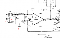
As a starting point I would suggest returning each sockets ground to the ground point that is shown connected to pin 3 of the chip in my diagram above. Make no other connection from the socket ground to anywhere else.
Now repeat the initial shorting test and then short the shorted inputs together (their grounds). It should be silent.
Hope that makes sense.
If that is the case then each amp is fine in isolation, but they are interacting when connected to a source component (which essentially links the L and R grounds together).
Again, that suggests that the ground wire from your input socket is returned to the wrong point.
As a starting point I would suggest returning each sockets ground to the ground point that is shown connected to pin 3 of the chip in my diagram above. Make no other connection from the socket ground to anywhere else.
Now repeat the initial shorting test and then short the shorted inputs together (their grounds). It should be silent.
From the beginning I thought he interchanged signal and ground on RCA.
Calling himself a beginner: shield is on outside and signal on inside joint
of RCA socket. Picture in post 15 does not show the essential wiring here.
But again how would a beginner detect signal wire from shield ?
OP changed the input wiring, everything was fine before so it is the input
wiring going wrong I guess.
However, observation in post 7 may lead to some other or additional
mischief. Re post 14 : ignore the output post for this "buzz" problem.
- Status
- Not open for further replies.
- Home
- Amplifiers
- Solid State
- quad 405 loud buzz