I have been doing some research on upgrading the 405. There is no point in getting 405-2 boards when upgrading this amp. I think I will do the upgrades recommended by Dada Electronics and also the PSU upgrades suggested by Nick de Smith. I was on Digikey earlier and I can get the main components for just under £50. The PSU smoothing caps have been replaced in my amp apparently. The boards will be issue 5 if I go by the serial number. I might skip using a pot and order the upgrade parts after I have had a look under the hood. I am going to work tonight and will make a definitive list of what I will need.
Quad as a company in those days was very reluctant concerning introducing new models, so introducing a MKII version was quite an event! If you have iss5 boards, a lot have to be changed to get to the latest 405-2 level, iss7, circuit diagram iss10. But will you hear the differance between a well revised MKI or MKII? That is depending on your speakers and front-end. If you use an amplifier within the design limits, the differance in 'sound' will be small. Can you give some examples of documents where they concluded; 'no point'? Not to blame the messenger, but I am very interested in the arguments.

According to Peter Walker, there were only two reasons to introduce a new model: either there had been some major technical breakthrough, like the introduction of stereo audio, or you had done it wrong the previous time.
Other changes in the QUAD 405-2 are the improved op-amp and the halved dead zone, but you can put those on a QUAD 405 board if you want.
Other changes in the QUAD 405-2 are the improved op-amp and the halved dead zone, but you can put those on a QUAD 405 board if you want.
I don't find all this talk of single-digit issue numbers very useful. The Quad 405 boards are numbered M12368, at least 10 issues, and M12565, at least 7 issues. Could we be more precise please.
We can 😉: M12368 iss 5, M12565 iss 7. The first I deduct from the remark that ElliJ did not want to swap over to 405-2 boards, so I asume he have 405-1 boards. The second is the last official version of the 405-2 board.
You are right that the mk2 boards are better. I plan to do some of the well documented modifications, includes changes to the current limiters. I picked up my amp today and have re-wired most of it. I left the 230v wiring as is and need some ring terminals for the psu caps. The little clamp circuit behind the speaker terminals was very tatty and had a couple of tracks lifting which I have repaired and con checked. All the caps have been replaced by the previous owner but I am not sure when. I just need to drill out some holes for the rca sockets and wire the psu caps and I can test it out. I am also making an in-line 12v trigger for the mains cable so I won’t have to turn it on and off.
Attachments
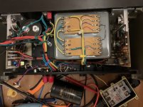
Are the TRIACs in good shape? They were short circuits in the QUAD-405 that I repaired about two decades ago.
If you perform such an extensive rewiring, I should also remove the mains voltage selector wiring, it is tiny and interferes with all the other wiring in the loom. Also conect the Tx wires directly to the rectifier and the chassis, not via the loom. On the GND point on the chassis there should be 4 wires connected, 2 speaker returns, one wire from the Tx centre tap and one from the centre connection between the two Psu Elco's. The gnd from the led can be connected to the connection wire between the two Psu elco's. In most countries the mains is 240V AC. In The Netherlands the voltage is around 235V, so wire the Tx for 240V, in this way you also use all the primary windings. In the DaDa Service manual there is also an example how to wire for 230V and us all the primary windings, but this is a little more complicated. In most cases the 240V setting will do perfect.
Marcel, are the Triads on the Clamp Circuit? If so I hope they are ok, I don’t want to take it out again.
Joost there is a GND wire from the Tx that goes to between the two PSU Elco’s. Are you saying this is wrong? I will check a circuit diagram. You are right, the Voltage Selector does get in the way of the loom. It also got in the way of a Clamp Circuit capacitor which I had to move to the other side of the board.
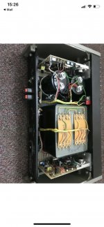
I might watch a YouTube video on lacing cord. Here is a picture of the amp before I touched it.
Joost there is a GND wire from the Tx that goes to between the two PSU Elco’s. Are you saying this is wrong? I will check a circuit diagram. You are right, the Voltage Selector does get in the way of the loom. It also got in the way of a Clamp Circuit capacitor which I had to move to the other side of the board.
I might watch a YouTube video on lacing cord. Here is a picture of the amp before I touched it.
Attachments
The TRIACs are in the clamp circuit. If they have become short circuits, they short the amplifier outputs. If you measure a hard short from the amplifier output to ground with the amplifier switched off, chances are that the TRIACs are not OK.
There is no 'wrong' it wil work, but there are better ways to do it, especially when you rewire the unit. I get the best results by using a large diameter wire between the two elco's. From one of the two eyelets a slightly smaller diameter wire connecting to the GND star point at the rectifier. Also connct the speaker return wires to the GND starpoint. Use solder eyelets for this, also for the connction of the plus and minus wires from the boards to the elco's. Use short wires to connect the secondary windings of the Tx to the rectifier and the GND starpoint. Remove the wires from the voltage selector and primary connections of the TX. Hardwire the primary windings to the mains chassis connector. To prevent stray fields, twist the wires which carry AC, leave the GND wires out of this twisting. If you want to look the cables neat and tidy use cable binders. Keep the low level input signal wires out of this new loom, to prevent coupling of unwanted signals.
Thanks Joost for all those tips. The amp is back together now and it sounds good. I cannot find an rca to rca lead anywhere in my house, I can’t believe I don’t have any! I have been streaming, listening to digitally stored music and using xlr cables for years. I had to use an rca to 3.5mm lead and a little hi-res music player to do a quick test. I’m looking forward to a proper test and after that will think about some upgrades. I was really worried it would blowup when I first plugged it in.
I got an rca cable and have been listening to the amp for a while. It sounds really good. One of the reasons bought this amp was because I found my class d amp to be fatiguing after an hour or so. There is quite a bit of noise that can be heard from about a foot away when the amp is idle so I have ordered a some new components from digikey (£62!!!). I plan to do the input sensitivity mod to 1.5V, the non-inverse input mod, replace T7, T8, T9, T10 and new opamps. T7 and T8 because there looks like 2 different ones on one board. There was not much choice of opamps I could use on digikey so I went for TLE2071. I will be changing all the electrolytic caps including on the clamp board which is not in very good condition so I did not want to remove it again. T9, and T10 are being replaced with MJ15003G. R30 and R31 are being replaced and moved further from the board, one of them looks burnt. Depending on how it sounds after this work I will think about a dual mono power supply. I also ordered some heat sink compound and some silicone tubing for my solder sucker (hopefully it will improve my desoldering). I can hear a pop when I turn the amp on is this normal?
I made a 12V trigger for the power cable which turned out really well. Just a tiny enclosure, relay and a 3.5mm jack socket.
I made a 12V trigger for the power cable which turned out really well. Just a tiny enclosure, relay and a 3.5mm jack socket.
With the standard Op-amp (TL071), a mild switch on noise (sound) is normal, switch off should be noiseless. With other op-amps the switch on and off sounds could be worse.
That’s good to know as it is silent switching off. The TLE2071 has been recommended on a few 405 mod pages. I did want to use OPA604 but there weren’t any on digikey. The current opamps are different on each board, one is a 301 but the other is unmarked.
I never dared to use the TLE2071 because its supply current much increases during clipping to the negative rail. I don't know what happens if that makes the Zener-diode-stabilized supply voltage collapse.
Keith Snook recommended the TLE2071, OP134 and OP604 in one of his papers. I wanted to buy all the components in one place to avoid delivery fees. Marcel do you mean when the amplifier is clipping at high volumes? Or that the opamp can clip too? Sorry, I am a mechanical engineer and my electrical theory is not great. I am ok soldering, following instructions, using a multimeter and triple checking everything.
I meant when you overdrive the amplifier so much that the op-amp clips, clips on the negative side. I don't know if anything does go wrong then, I just couldn't prove by calculations that nothing can go wrong then.
- Home
- Amplifiers
- Solid State
- QUAD 405 Input Sensitivity