All,
A Quad 405 for repair needs to have its PCBs re-done and I thought that I might as well put the 405-2 variant in there for the same amount of trouble: audio reviewers claim the 405-2 is definitely better than the 405-1, which I will be happy to verify once a board is built. I have read the warnings in another thread on how to avoid oscillation -- I will use Quad's PCB layout (M12565 Issue 7), parts list etc. I'm not sure about copyrights, but I suppose one is probably allowed to repair an existing unit for which the warranty has expired since many years...
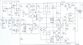
The current limiter circuits (shown as N1 and N2 in the circuit diagram) raises a few question marks. Though it is not necessarily required, it might be worthwhile to have it in the finished version.
I suppose its functionality will be OK if I materialise it as a concrete classical small PCB and not as a thick film circuit. The circuit diagram, however shows a PNP transistor with its emitter connected to pin 4 while it is labeled as a BCW60 -- which is an NPN if I'm not too much mistaken. From its position in the general circuit, I would assume an NPN is to be used...
Is this just a 'typo error' in Quad's circuit diagrams (it appears like that in all diagrams I have found) and can I use an NPN (e.g., a BC550C)?
My 'soldering' experience is more in the area of digital circuits and the heaviest end amplifier I ever built so far was a solid-state 15W RMS thing, so any other caveats & usful warnings will be appreciated as well.
Thank you for sharing your insights,
--
Jacques
A Quad 405 for repair needs to have its PCBs re-done and I thought that I might as well put the 405-2 variant in there for the same amount of trouble: audio reviewers claim the 405-2 is definitely better than the 405-1, which I will be happy to verify once a board is built. I have read the warnings in another thread on how to avoid oscillation -- I will use Quad's PCB layout (M12565 Issue 7), parts list etc. I'm not sure about copyrights, but I suppose one is probably allowed to repair an existing unit for which the warranty has expired since many years...
The current limiter circuits (shown as N1 and N2 in the circuit diagram) raises a few question marks. Though it is not necessarily required, it might be worthwhile to have it in the finished version.
I suppose its functionality will be OK if I materialise it as a concrete classical small PCB and not as a thick film circuit. The circuit diagram, however shows a PNP transistor with its emitter connected to pin 4 while it is labeled as a BCW60 -- which is an NPN if I'm not too much mistaken. From its position in the general circuit, I would assume an NPN is to be used...
Is this just a 'typo error' in Quad's circuit diagrams (it appears like that in all diagrams I have found) and can I use an NPN (e.g., a BC550C)?
My 'soldering' experience is more in the area of digital circuits and the heaviest end amplifier I ever built so far was a solid-state 15W RMS thing, so any other caveats & usful warnings will be appreciated as well.
Thank you for sharing your insights,
--
Jacques
Attachments
Hello Jaques!
Are you aware of the Berndt Ludwig mods to the 405(-2)?
Please have a look here:
For some iimediate improvement:
- dump the TL071 opamp at the input, use an OPA134 or similar, add suitable bypass at the supply pins, see spec sheet
- change all elcos, increase the big ones to 15000uF.
What concerns the current limiters, gently desolder N1 and N2 and politely say goodbye before they enter the garbage bin (you are not using ESL57 are you?)...
Check Net-Audio for more commercial upgrades to the 405 - link
Good luck!
Thomas
At one stage I knew people at an EMI military factory building the 405, so they were probably to blame for the hybrid.
I thought that the triac on the output is the protector for the electrostatics, they are extremely peak voltage sensitive unlike normal speakers which are only power dissipation sensitive.
I thought that the triac on the output is the protector for the electrostatics, they are extremely peak voltage sensitive unlike normal speakers which are only power dissipation sensitive.
The triac on the output is to prevent potentially damaging dc offsets from appearing at the output. The output feeds through an R-C filter so that if a large enough dc offset appears at the output, the triac crowbars and short-circuits the output.
So, if you have removed the current limit circuitry on your 405, perhaps it also makes sense to remove the output triac boards as well!
So, if you have removed the current limit circuitry on your 405, perhaps it also makes sense to remove the output triac boards as well!
Hello Thomas,
Yes, I know about Bernd Ludwig's recommendations for improving a 405 and I intend to apply at least the op-amp improvement (with its decoupling capacitors) and some other things which I have yet to sort out. The power supply capacitors need replacement as well, they look as if they will explode any moment.
I want to replace the existing 405-1 boards (which appear to have been treated badly) with new 405-2 ones, with all new components, hence my question about this limiting circuit. At least I can re-use the T-profile heatsink mounting stuff...
I understand that the N1/N2 circuits have a different purpose than the X1 shortening link (to be applied when using Quad 57 ESLs): they limit the current into bad load impedance (below 3 Ohm), hence 'protect' the output transistors whereas the X1 link limits the output voltage at maximum 26V, protecting the vintage ESL57 speakers one may have.
The N1/N2 current limiting circuits are supposed to be an improvement over the older T5/T6 circuitry; reviewers in the audio press (early 1980s) claimed that the difference was audible.
Best regards,
--
Jacques
dunno if the current limiter does anything to protect the components...a short circuit blows the output transistor(s) and the fuse...
anyway, there's a company on the net selling modded 405 cards at a cost. Don't remember the name, but I'm sure a search will help, the're mentioned on this forum, too
anyway, there's a company on the net selling modded 405 cards at a cost. Don't remember the name, but I'm sure a search will help, the're mentioned on this forum, too
Hi,
the triac is shown across the output to return.
Can a pair of these triacs be connected from Vcc and Vee to return and simply blow the PSU supply fuses?
Would this still save the speakers and not damage the output stage?
the triac is shown across the output to return.
Can a pair of these triacs be connected from Vcc and Vee to return and simply blow the PSU supply fuses?
Would this still save the speakers and not damage the output stage?
If the 405 still has the original current-limit circuitry, the output triac 'crowbar' circuit will not damage the output transistors. The possibility of damage is if the crowbar clamps the output on a board in which the output current limit has been increased to allow the 405 to drive 100W into 4R loudspeakers.
As you say, the BCW60 is NPN, and if you look to the right of the PNP one, there's another BCW60 correctly drawn. So it's just an error with the diagram, using the wrong symbol.
Zombie said:[snip]What concerns the current limiters, gently desolder N1 and N2 and politely say goodbye before they enter the garbage bin (you are not using ESL57 are you?)...
[snip]
These are not current limiters. These are safe operating area limiters. One of the main differences btween the -1 and the -2 is in the improved protection system. The -2 system limits the operation area of the output stage to protect blowing up the output devices. They do not just limit current to some arbitrary value. Throwing them out is a bad idea; they will not limit the power under normal conditions, but will protect the amp in case of shorts and prolonged overload.
Jan Didden
I would like to see new circuit boards for the Quad 405, combining the frontend of Keith Snook and the Audio Linear output (6 output transistors per channel) and with the N1/N2 networks. Anyone who want to do that? I do not have the knowledge for it...
RogerGustavsson said:I would like to see new circuit boards for the Quad 405, combining the frontend of Keith Snook and the Audio Linear output (6 output transistors per channel) and with the N1/N2 networks. Anyone who want to do that? I do not have the knowledge for it...
Would that still keep the current dumping concept (the ingenious combination of pos and neg feedback) of the amp? Or will it, in effect, become a 405 box with an entirely different amp?
Jan Didden
Not about the limiter circuit, but...
Once upon a time, the BBC had an awful lot of (BBC-designed) active loudspeakers designated LS5/8 that were their best monitoring loudspeakers. They used a 12" polypropylene woofer crossed over to a Son Audax 37mm soft dome tweeter using an active crossover and a Quad 405/II. Seeing the relative sizes of the drivers, you will ask, "Where's the midrange driver?" If I then tell you that these loudspeakers made all female vocalists sound like Elkie Brooks and all male vocalists like Tom Waits, you will feel that your question was justified. However, the sting in the tail is that someone tried substituting a Chord amplifier for the 405 and it transformed the loudspeaker. Before long, this was a recommended upgrade...
My point is that although the current dumping concept was innovative (sparked lots of letters in "Wireless World"), nobody copied it, and Quad themselves abandoned it.
Quad still make amps with current dumping - Quad 909, and before that the 306, 707, 510, 520 (and all theo ther 5** pro models)
Zombie said:Quad still make amps with current dumping - Quad 909, and before that the 306, 707, 510, 520 (and all their 5** pro models)
I stand corrected. I'm sure we had a Quad at work some years ago, and since all Quads came with a diagram, I looked at it and it was a standard Lin circuit. A 606, perhaps?
All the Quad 606, 707, and 909s have been current dumping. I've not seen a 'Lin' type quad since the 303.
janneman!
The answer to your question is yes. Keith Snook's frontend is here:
http://dc-daylight.ltd.uk/Valve-Audio-Interest/QUAD/QUAD-405 Modification/QUAD-405-mods.html
The Audio Linear 405 follows Bernd Ludwig's modification but uses 6 output transistors instead of Bernd's 4.
http://www.audiolinear.com
I would like to clean up the area around the input of the Audio Linear board. More space for capacitors and perhaps add a balanced input with the help of an INA137 (gain=2). That would make a further gain reduction possible for the "frontend IC" (OPA604, OPA134 etc.), and smaller value capacitors could be used as well. The N1/N2 networks and the output clamp (DC-protection) should be retained.
- Status
- Not open for further replies.
- Home
- Amplifiers
- Solid State
- Quad 405-2 limiter circuit