I purchased my amp back in 1983. Its serial number is 67320. A while ago I noticed a high level of hum on one channel and after researching this decided to change all the electrolytic caps on both boards. These were C10, C18, C19, C5, C2 and C17. Many had almost zero capacitance.
I powered the amp to discover that it was getting very hot on both pcb. I then checked what I had done and discovered I had made an error in fitting a standard electrolytic in C17 position instead of a bipolar !
I then ordered up the correct non-polarised caps and fitted them. Unfortunately this did not fix the problem. Measuring the + and - supply volts I found the positive was OK at 50V however the negative rail had dropped to about 45V. Checking the current through the negative rail fuse on the amp pcb the current was about 3.7A.
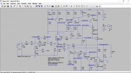
The amp pcb are type M12565.6
So looking for ideas of what I might have damaged by fitting the wrong type of caps. Is it possible that I have damaged the Diac T1 ?
Any help appreciated.
I powered the amp to discover that it was getting very hot on both pcb. I then checked what I had done and discovered I had made an error in fitting a standard electrolytic in C17 position instead of a bipolar !
I then ordered up the correct non-polarised caps and fitted them. Unfortunately this did not fix the problem. Measuring the + and - supply volts I found the positive was OK at 50V however the negative rail had dropped to about 45V. Checking the current through the negative rail fuse on the amp pcb the current was about 3.7A.
The amp pcb are type M12565.6
So looking for ideas of what I might have damaged by fitting the wrong type of caps. Is it possible that I have damaged the Diac T1 ?
Any help appreciated.
I suspect you have other issues tbh. Whilst C17 must be a bipolar, under quiescent conditions it actually doesn't matter as there should be zero volts DC at the speaker terminals.
So C17 shouldn't even come into the equation here. If you suspect the Triac is firing then just temporarily add a link across C17 but on no account connect speakers.
I actually suspect you have created a fault that is causing a high negative DC offset. So you must confirm that by disabling the Triac and then measuring the offset. With luck the over current protection has saved the output transistors.
If the power supply is still intact and you aren't playing any music, then that is consistent with a path from the negative rail to earth of ~15ohms. I'd look at the schematic and ask "how do manage to achieve such a low resistance?". Then I'd disconnect everything and put a meter on it to find whether such a path exists.
Since you have a second channel which works, use the meter to work out the difference between the two boards.
kind regards
Marek
Since you have a second channel which works, use the meter to work out the difference between the two boards.
kind regards
Marek
I suspect the 'path' is via the Triac and the current is limiting at around 3.7A because of the limiter circuit across R36.
I tried the simulation I have of the 405 under these conditions and it limited at -4.7A but that is actually a pretty close result given that the sim has no resistive losses and will also have different transistor model characteristics.
Q7 could be a prime suspect, either dries on it or intermittent failure which is a known failure mode for these type of devices, particularly when they run hot.
Thanks both for your replies.
I have had both boards (which both overheat) side by side looking for differences but everything I measure looks identical. I am using a Fluke 21. Spent 2 hours on this !
Q7 (TR7 ?) is an RCA40872. It measures fine in circuit and I cannot see any dry joints.
Yes I also think that the current is flowing through the triac however not sure why it is turning on ? Later today I will try putting one of the original C17 ROE 10uf Bipolar caps back in circuit just in case therer is something special about them. The old ones measure about 4 and 6 uF respectively.
Will come back later after some more work.
Later today I will try putting one of the original C17 ROE 10uf Bipolar caps back in circuit just in case therer is something special about them.
Don't even bother, the best thing you did with those caps is remove them, they will be toast.
There is nothing special about the originals, apart from them being a bipolar cap.
Replace them in any amp if ever you see them.🙂
If you remove the Triac you remove that route. Nothing bad (or lets say worse than it is now 😉) can happen provided you do not connect speakers. If it is all on a separate board then just isolate the triac board
If you short the cap (C17) out then you remove the ability of the triac to turn on. That is fine as long as the triac itself has not failed. In which case you just remove it or isolate the board as a test.
If you short the cap (C17) out then you remove the ability of the triac to turn on. That is fine as long as the triac itself has not failed. In which case you just remove it or isolate the board as a test.
Decided to try shorting C17 as per Mooly suggestion. With power applied I had full 52.5 volts on both positive and negative rail and nothing was getting hot. Next I took the board back out of the amp and after removing the short changed C17 back to one of the ROE originals. On the capacitance meter this measured about 8 uF. Again the amp powered normally with no overheating. Measuring the one I had taken out it measured 12 uF.
Not sure why the amp should be OK with an 8 and not with a 12 uF ? Any ideas ?
Has anyone replaced C17 ? And if so what make did you use ? Maybe they have to be selected to be less than 10 uF ?
Not sure why the amp should be OK with an 8 and not with a 12 uF ? Any ideas ?
Has anyone replaced C17 ? And if so what make did you use ? Maybe they have to be selected to be less than 10 uF ?
It sounds very odd tbh. The cap and the 15k resistor form a filter that also slows down the rise time of any sudden DC voltage that may appear at the output.
A bigger cap should make the triac less prone to trigger. You should be able to fit a 100uF or a 1000uF there and the only effect would be to make it less and less effective as a protection circuit.
It doesn't compute 🙂
So does the amp work normally now?
A bigger cap should make the triac less prone to trigger. You should be able to fit a 100uF or a 1000uF there and the only effect would be to make it less and less effective as a protection circuit.
It doesn't compute 🙂
So does the amp work normally now?
With power applied I had full 52.5 volts on both positive and negative rail and nothing was getting hot.
So both rails were ok, what about DC on the output?
What about +-12v on the op amp (pin 4 and 7 with respect to deck)? present?
Checked the op amp on one board and it has 14.35v on pin 4 and 14.98v on pin7. The zener diodes are 15V so not far off,
In order to test the other board I changed C17 back to the original and all now normal with no overheating. In circuit I could only measure pin 4 of the op amp which was 15.5v. Will try and get pin 7 tomorrow.
Measuring on the output terminals with no load I get -3.9v to earth and on the other 10.1v. This is far too high and probably explains why the triac was triggering.
Think I need to do some more looking at the pcb tomorrow !
Those are strange voltages for a 'DC fault' because typically such faults simply cause the output to shift toward one or other of the rails.
The one check I would do would be to look at the output on a scope to make sure the amp was not oscillating. Anything like that could give an apparent shift in DC when in reality the reason a very asymmetric HF signal at the output.
I would also go back over all your work and make sure caps are fitted correctly with regard to polarity. Do not trust board markings as they can be in error on occasions. Confirm values and polarity by looking at the circuit diagrams and by measuring actual voltages across the caps.
Make sure non are under rated voltage wise and so causing a leakage upsetting DC conditions.
I have checked the boards over carefully and all caps are fitted correctly. The only one I have some doubt about is C2. The new cap is fitted the same way as the original however looking at various diagrams there seems to be some debate about which way this should be fitted.
Yesterday I cannibalised an old 15 ohm speaker to test the amp instead of using the LS3/5A in case I damaged them. Using a Quad 44 pre-amp and CD player I fed the 405 through the normal cable. On connecting the speaker to one of the amps the DC voltage on the output dropped to a few millivolts however no audio output.
On the other amp the 10 volts dc on the output was unaffected by the speaker being connected and there was also no audio output.
Unfortunately I don't have a scope so can't check for oscillation.
I would buy a couple of opamps but not sure if it is worth it. I am tempted to buy a couple of these from Ebay item number 123449394375. Has anybody else tried these clones ?
C2 should have a very small DC voltage across it, almost zero volts in normal operation. Whenever there is doubt about polarity simply measure the actual voltage across the cap and see how that shapes up.
What opamp is fitted in yours? Is it an LM301?
I would be surprised if an opamp were at fault tbh. Careful voltage checks could give a clue.
These would be expected voltages within the amp. The critical opamp voltages are the two supplies on pin 4 and 7 and the two inputs on pins 2 and 3 and also the output on pin 6.
Attachments
Decided to start checking components again and I have discovered that R7 is open circuit on 1 pcb. Also I have found something strange...
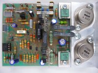
There is a resistor (At least it looks like a resistor) of 4.7K ohm that is across D2 that on the solder side of the pcb is marked C20 ? I have looked at the diagram for this pcb M12565.6 and it says it should be a capacitor. Will remove tomorrow and check to see if it has capacitance. Have attached a pic of a similar pcb to mine. Resistor/capacitor is in the bottom LH corner.
There is a resistor (At least it looks like a resistor) of 4.7K ohm that is across D2 that on the solder side of the pcb is marked C20 ? I have looked at the diagram for this pcb M12565.6 and it says it should be a capacitor. Will remove tomorrow and check to see if it has capacitance. Have attached a pic of a similar pcb to mine. Resistor/capacitor is in the bottom LH corner.
Attachments
R7 is the supply feed to the opamp. It would be a classic failure item with no contributary causes. R8 is similar.
The part in your picture looks like a cap, that style was used in much commercial equipment... and I can't for the life of me think what they are called and can't find any pictures of them either.
Multilayer ceramic capacitor, and they are so common... where are they all 😀
They do exist though. Really.
The op-amp is an OPA134, don't those draw too much current for the Zener diode supply?
Edit: My mistake: it's an OPA134 on a picture of a similar board, so that doesn't mean anything.
Edit: My mistake: it's an OPA134 on a picture of a similar board, so that doesn't mean anything.
Last edited:
Had some success today. Replaced R7 and cleaned up solder joint on R10. Tested amp and it works !
I have also found the fault on the other pcb. It was one of the RCA17556 that has failed. From searching around it seems that an MJ15003 is a good replacement. Would you recommend replacing both ? Both the 40872 seem to be OK.
I have also found the fault on the other pcb. It was one of the RCA17556 that has failed. From searching around it seems that an MJ15003 is a good replacement. Would you recommend replacing both ? Both the 40872 seem to be OK.
- Home
- Amplifiers
- Solid State
- Quad 405-2 high current problem