Hello, I'm new on this forum. As I have read another thread relative to the Quad 306, I told to myself that I could perhaps find some help here.
So, my 306 shows a strong distortion on left channel as soon as the level is not at minimum.
When used with a Quad 34 preamp, the sound is strongly distorted, on the left channel only, as soon as the volume knob is over 1 or 2. The right channel is ok.
The seller told me that the amp was never serviced since he bought it new in the 80's.
The first thing I did was replacing the four 4700μF electrolytic capacitors, but that didn't change the problem.
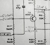
I measured every tension noted on the schematic, and nothing seems abnormal. You can read the values on the attached picture.
So now, I wonder where to investigate?
Thanks in advance for your advices. And sorry for English is not my language.

So, my 306 shows a strong distortion on left channel as soon as the level is not at minimum.
When used with a Quad 34 preamp, the sound is strongly distorted, on the left channel only, as soon as the volume knob is over 1 or 2. The right channel is ok.
The seller told me that the amp was never serviced since he bought it new in the 80's.
The first thing I did was replacing the four 4700μF electrolytic capacitors, but that didn't change the problem.
I measured every tension noted on the schematic, and nothing seems abnormal. You can read the values on the attached picture.
So now, I wonder where to investigate?
Thanks in advance for your advices. And sorry for English is not my language.
Diode test seems ok, but I'm not sure of what to test.
Here are the pin voltages, no signal applied.
Base voltage is the same on L and R after a few seconds but when I put the probe on left T8 base, I can read up to -1200mV before it goes down to -645mV. This does not happen on right T8 base.
Is it a clue?
Here are the pin voltages, no signal applied.
Base voltage is the same on L and R after a few seconds but when I put the probe on left T8 base, I can read up to -1200mV before it goes down to -645mV. This does not happen on right T8 base.
Is it a clue?
Attachments
Without thinking, I'd replace C11. The only other electrolytic on the schematic. Quad is to be praised for not using more of these time fuses. I buy >2000 hour service life e-caps to avoid doing the job again 4 times as I did using store shelf parts.
Other usual suspect, Q7 & Q8 are drivers. Often blow because cost cutting prevented putting a heat sink on them. These things run hot usually. Pull base lead and do double diode check. If doesn't fail that a Iceo test may be in order. DVM test at 2 v or less, parts sometimes only fail at elevated voltage. I use a 12 v battery charger and a 47k resistor series the milliamp scale of DVM. I=V/47k, your transistor just broke down.
3rd usual suspect, zener diodes D1,2,3,4. These can be measured in circuit for proper voltage. Use an alligator clip lead for one point, never use 2 hands with the power on.
If replacing the obvious doesn't work, you'll need a sine wave generator and a sound probe or oscillosope. You'll have to trace the wave form into the circuit starting at the input jack and find out the first stage that distorts. Then start testing & probing items around there. Could be a bad solder joint but those usually fail at low volume, not high volume.
Warning, working an amp with the power on can be dangerous. Connect instrument grounds to the analog ground with an alligator clip lead. Junction C10 & C11. Never use two hands power on. >24 volts across the heart can stop it. If you're impulsive put one hand in your pocket. Wear no jewelry on hands wrists or neck, 1 v @ 30 amps through a ring can burn your flesh to charcoal. Wear safety glasses, parts can explode and solder splashes, especially desoldering.
If you don't have a scope probe, a meter tip can often short two items together and damage a component. If using a meter buy a Pamona grabber lead for it, or a Q-ball who invented the things. That short tip is too short to short two conductive items.
Last edited:

R 23 & T4 are used as a current limiter .... if R23 is open or above nominal value ... or T4 fail ... protection will will work even at low level.
I buy >2000 hour service life e-caps
Electrolytic life ratings are commonly quoted at 2000 hours to allow direct comparison - its the temperature that matters - the higher the 2000 hour temperature the better they are - most caps are not used near the "rated" temperature and thus last much longer than that nominal 2000 hours. So getting 2000hour 105C caps may actually be better than 10000hour 85C caps, as thermal issues are typically exponential with temperature, due to the Arrhenius relationship.
My experience contradicts this statement. Is the Arrhenius statement about the aluminum foil? UPS supply vendors worry about that. My e-caps dry up, have too high ESR and rarely short. Mostly the power goes down on amps, the sound gets weird on organ oscillators & filters as frequency effects change. Tantalums had a 95% failure rate in 1964-68 products I own.So getting 2000hour 105C caps may actually be better than 10000hour 85C caps, as thermal issues are typically exponential with temperature, due to the Arrhenius relationship.
I use my main amp & radio ~2000 hours a year. I got 6 to 8 year life out of store shelf caps. Sprague Atomlytics & Blue Beavers had no life rating, I have a 1966 Sprague catalog binder. I've replaced about 400 e-caps since I quit working in 2008. Most were 85 C rated, 3000 hours on big caps except when I couldn't get better, and 5000 hours up on small caps. None has needed replacing again. Not even on the amp I turn on when I wake up & off when I turn out the lights. .My suspicion is that there is red gum rubber sealant in cheap caps, some kind of exotic elastomer in the long life ones. Yes, the 105 C caps are holding up too, but there are not many of those. E-caps in DTV converters and cheap computer power supplies don't even last a year.
Last edited:
I have a Sony HDD recorder (for digital TV) and that has been powered up since around 2008. The PSU was recapped about 4 years ago and the removed caps tested on a Tanϴ meter. All were excellent and essentially little different to the new replacements.
@Mark Tillotson is correct and you have to be very careful when comparing specs and be sure to check out the actual test conditions used.
@Mark Tillotson is correct and you have to be very careful when comparing specs and be sure to check out the actual test conditions used.
R23 measure 0.1Ω both channel.R 23 & T4 are used as a current limiter .... if R23 is open or above nominal value ... or T4 fail ... protection will will work even at low level.
T4 seem ok.
I have to investigate on R6, because I have strange measurements on this one.
By the way, I work with the M12890-3 board schema, but my 306 has the M12890-4 board. Where could I find a print of this version?
I've not seen any other version of the 306 service manual than the usual one floating around on the 'net, which covers only PCB versions 2 and 3. I read that there were 6 versions in all but it's likely others were mostly about power supply wiring and connections as may have been altered to suit different transformers and wiring for different countries or availability. So, the distribution of service manual updates could have been quite restricted or supported only by notes, a loose couple of pages etc. sent only to affected service agencies.
When I find a service manual that actually has a PCB pattern with parts layout, I simply place a fluoro tube (i.e. diffuse light) desk lamp behind the board, to view the copper traces with components fitted and then compare that with the published schematics. It's nice to have this visual support of seeing and tracing out the physical circuit copper to help with understanding but if I'm serious about getting a job done, I find it essential to follow and rely primarily on the schematic diagram and part numbers.
When I find a service manual that actually has a PCB pattern with parts layout, I simply place a fluoro tube (i.e. diffuse light) desk lamp behind the board, to view the copper traces with components fitted and then compare that with the published schematics. It's nice to have this visual support of seeing and tracing out the physical circuit copper to help with understanding but if I'm serious about getting a job done, I find it essential to follow and rely primarily on the schematic diagram and part numbers.
I would investigate the feedback portion starting with R22. An old Sansui was doing the same thing and the distortion wasn’t audibly bad but definitely measurable. A resistor in the feedback path had drifted just out of spec but that alone wouldn’t cause it. The resistor was just noisy.
ive had resistors go high on QUAD amps cracks appearing on surface, check all resistors for correct value
Here are some measurements I made, hope this can help to find the issue (for memory right channel is OK, left channel has distortion) :
Voltages on T7, T8, T9, T10, no signal, 4 ohms speakers :
T7 R channel
C-B : 39.2V
C-E : 39,7V
E-B : -0.6V
T7 L channel
C-B : 40.3V
C-E : 40.9V
E-B : -0.6V
T9 R channel
C-B : -41.3V
C-E : -41.5V
E-B : 0.07V
T9 L channel
C-B : -42.3V
C-E : -41,5V
E-B : -0.68V <--
T8 R channel
C-B : 37.5V
C-E : 37.9V
E-B : -0.6V
T8 L channel
C-B : 37.2V
C-E : 38.6V
E-B : -0.5V
T10 R channel
C-B : -38.2V
C-E : -38.7V
E-B : 0.5V
T10 L channel
C-B : -38.6V
C-E : -38.9V
E-B : 0 <--
I made also some measurements on D5 to D8 and I have have noticed a big difference on D8 :
D5 R : 702mV
D5 L : 679mV
D6 R : 702mV
D6 L : 694mV
D7 R : 717mV
D7 L : 706mV
D8 R : -75mV
DB L : +688mV <--
What should I check now ?
Your getting some great help here 🙂
Have to ask if this was the other thread you looked at?
https://www.diyaudio.com/community/threads/quad-306-high-dc-offset-in-left-channel.384125/
The final issue was distortion as you describe and the problem was TR8 in the end. Although you could swap TR8 between channels (and that was done in that thread) that can sometimes actual temporarily 'fix' issues with faulty transistors. The problem was not obvious via simple DC measurements.
It might be worth trying. If the fault remains then obviously it's not that. If the fault changes channel then its faulty, and if both channels suddenly work then its also going to the transistor at fault.
Yes, I looked as this other thread and this is why I thought I could find help here ;-)
I'll swap TR8 and report the results here.
Thank you.
I'll swap TR8 and report the results here.
Thank you.
So, swapping made and... distortion gone !!
But, when desoldering and separating Tr8 L from the radiator, one leg broke. Or was it broken before ? Or was it a cold solder ? I'll never know.
I made a repair when swapping the transistors, and before sending a signal, I checked the values on D8, and I read the same value on R and L. Good !
Then I played music and everything was fine.
What's your opinion on this result ?
The fact you swapped it and the fault is now fixed kind of proves there was some issue... exactly what we may never know without actually having been there and seen it 🙂
I'm not sure if you are saying you have 'repaired' the lead and refitted the same transistor or replaced the transistor for new but only a replacement will be a guaranteed fix for this. The heat of soldering it may well temporarily 'fix' an intermittent device,
I'm not sure if you are saying you have 'repaired' the lead and refitted the same transistor or replaced the transistor for new but only a replacement will be a guaranteed fix for this. The heat of soldering it may well temporarily 'fix' an intermittent device,
I repaired the broken leg, as it broke a few mm after the plastic case. And I am listening to the 306 since then, with no issue.
It is said in the service manual that new "Sil" pads must be used when replacing a driver or output transistor. What kind of material is it?
It is said in the service manual that new "Sil" pads must be used when replacing a driver or output transistor. What kind of material is it?
They could be synthetic (flexible and bendy and often used 'dry) or they could mica which is clear and brittle and usually used with a thermal paste on each side.
If it is undamaged then it will be fine and assuming it is a TO220 outline device it will be like this:

If it is undamaged then it will be fine and assuming it is a TO220 outline device it will be like this:
- Home
- Amplifiers
- Solid State
- QUAD 306 distortion on left channel