Some time ago I bought a box of hardware on a second hand site , that contained a Quad 303 enclosure , among other interesting hardware.
I allso had some Quad 405 sinoclono boards and I decided to assemble a Quad 305, which is the Quad 303 enclosure with the Quad 405 boards and a
2x18V toroid , allso found in the box of hardware. To make things interesting I decided to use my small supply of ancient silicon and germanium
power transistors. Those were the BC141/341/361 NPN/PNP transistors the 2N2219A as the class A amp and the germanium 2SB361 as current dumpers
and maybe the AC151. For the opamp I plan to use an allso very old NEC C157c , which is a LM301A clone. All in nice TO-99 and TO-39 housings and the power transistors are TO3,
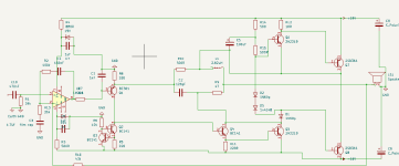
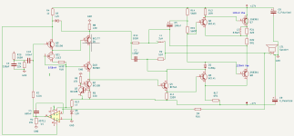
The 405 dumpers are NPN types , so I have to inverse the layout of the 405. I took the Keith Snook modifications and reversed all the NPN and PNP transistors
to comply with the PNP current dumpers. See attached schematic. I removed some windings from the 2x18V toroid to become a 2x15V transormer, supplying
ca. ±20V to the circuit, enough for a 2x15W amplifier. In the schematic the 1n60p diodes are germanium if I can find them, otherwise I will use 4 of the 8 AC151 I have as diodes.
Question, is this a valid circuit. I tried to make adaptations to the values of R14/15 to get ca. 20mA in the class A stage and R12 to get ca. 0.2 Vce for the 2SB361. Is that correct ?
Because the dumpers are essentially working in class C , I thought germanium transistors are excellent for that, being fragile components. Their (very) low Ft is nicely appropriate too.
I tested the boards with the normal components with the keith snook mods and it works very well on ±26V, with the bootstrap resistors scaled down to 280 Ohm to get to the 50mA
for the class A driver, it delivers 4Volt in 8Ohm resistive load without the dumpers installed, but at that level the driver was starting to release fume, or the cooling paste , I switched off before I could
determine where the smoke originated from.
I plan it to be the stand-in for my 8Watt Taylor T20 based SET amp, that is quite energy hungry, with a constant power draw of more than 100Watts. This one will use hardly 5Watts under normal use. My average listening level is 0.1 to 1 Watt so the 15Watts it might produce is more than enough and is on par with the amps I had all my life , the sansui AU101 and AU117.
I have only 4 2SB361, salvaged from a Nikko TRM-40ic and they are no longer made, so I have to be carefull. Is the reversal of the polarity of the transistors done correctly ?
Is the bridge still valid in this reversed setup and low working voltages and decreased class A standing current? From several sources I understood that for the bridge to be balanced the 500 and 47
Ohms resistors multiplied needs to be equal to the inductor 2.82uH and the capacitor of 120pF divided, which is true for these specific values , but when I read the schematics of the Quad 306 or 606
it doesn't need to be seemingly, because there the equality is far off, or are there other factors involved in the bridge balance besides the values of the two resistors and the inductor and capacitor, like e.g. the gain of the amplifier or the input circuit, which are seriously different between the 405 on the one hand and the 306 and the 606 on the other.
In the schematics , the BC361 pnp is the input of the dumpers gain block. I contemplated using a AC151 germanium pnp there , but the AC151 has half the Hfe of the BC361. Would it be possible to reduce the gain of the dumper block and increase the gain of the opamp, or is the gain of the dumper block of influence on the bridge balance ? E.g. decrese the 500 Ohm feedback resistor to 300Ohm and increase the 120pF capacitor to 200pF. I only need 11V to get to the 15Watts in 8Ohm , so a total gain of 11 is enough for an input sensitivity of 1Volt.
Thanks for reading and commenting, and just to be clear ,I don't expect or want a magical sound improvement because of the use of germanium transistors , just a fun project with old parts, to see if it works and if I understood the workings of the current dumper principle.
Systux
I allso had some Quad 405 sinoclono boards and I decided to assemble a Quad 305, which is the Quad 303 enclosure with the Quad 405 boards and a
2x18V toroid , allso found in the box of hardware. To make things interesting I decided to use my small supply of ancient silicon and germanium
power transistors. Those were the BC141/341/361 NPN/PNP transistors the 2N2219A as the class A amp and the germanium 2SB361 as current dumpers
and maybe the AC151. For the opamp I plan to use an allso very old NEC C157c , which is a LM301A clone. All in nice TO-99 and TO-39 housings and the power transistors are TO3,
The 405 dumpers are NPN types , so I have to inverse the layout of the 405. I took the Keith Snook modifications and reversed all the NPN and PNP transistors
to comply with the PNP current dumpers. See attached schematic. I removed some windings from the 2x18V toroid to become a 2x15V transormer, supplying
ca. ±20V to the circuit, enough for a 2x15W amplifier. In the schematic the 1n60p diodes are germanium if I can find them, otherwise I will use 4 of the 8 AC151 I have as diodes.
Question, is this a valid circuit. I tried to make adaptations to the values of R14/15 to get ca. 20mA in the class A stage and R12 to get ca. 0.2 Vce for the 2SB361. Is that correct ?
Because the dumpers are essentially working in class C , I thought germanium transistors are excellent for that, being fragile components. Their (very) low Ft is nicely appropriate too.
I tested the boards with the normal components with the keith snook mods and it works very well on ±26V, with the bootstrap resistors scaled down to 280 Ohm to get to the 50mA
for the class A driver, it delivers 4Volt in 8Ohm resistive load without the dumpers installed, but at that level the driver was starting to release fume, or the cooling paste , I switched off before I could
determine where the smoke originated from.
I plan it to be the stand-in for my 8Watt Taylor T20 based SET amp, that is quite energy hungry, with a constant power draw of more than 100Watts. This one will use hardly 5Watts under normal use. My average listening level is 0.1 to 1 Watt so the 15Watts it might produce is more than enough and is on par with the amps I had all my life , the sansui AU101 and AU117.
I have only 4 2SB361, salvaged from a Nikko TRM-40ic and they are no longer made, so I have to be carefull. Is the reversal of the polarity of the transistors done correctly ?
Is the bridge still valid in this reversed setup and low working voltages and decreased class A standing current? From several sources I understood that for the bridge to be balanced the 500 and 47
Ohms resistors multiplied needs to be equal to the inductor 2.82uH and the capacitor of 120pF divided, which is true for these specific values , but when I read the schematics of the Quad 306 or 606
it doesn't need to be seemingly, because there the equality is far off, or are there other factors involved in the bridge balance besides the values of the two resistors and the inductor and capacitor, like e.g. the gain of the amplifier or the input circuit, which are seriously different between the 405 on the one hand and the 306 and the 606 on the other.
In the schematics , the BC361 pnp is the input of the dumpers gain block. I contemplated using a AC151 germanium pnp there , but the AC151 has half the Hfe of the BC361. Would it be possible to reduce the gain of the dumper block and increase the gain of the opamp, or is the gain of the dumper block of influence on the bridge balance ? E.g. decrese the 500 Ohm feedback resistor to 300Ohm and increase the 120pF capacitor to 200pF. I only need 11V to get to the 15Watts in 8Ohm , so a total gain of 11 is enough for an input sensitivity of 1Volt.
Thanks for reading and commenting, and just to be clear ,I don't expect or want a magical sound improvement because of the use of germanium transistors , just a fun project with old parts, to see if it works and if I understood the workings of the current dumper principle.
Systux
Attachments
For one, the LM301 is not stable without compensation. Check the TI datasheet of the LM301AN for calculation of the compensation capacitor.
Nice project. In 1980 I also built a class AB amplifier with a LM301 as input. A friend of mine built a clone of the Quad 405. It sounded excellent.
Nice project. In 1980 I also built a class AB amplifier with a LM301 as input. A friend of mine built a clone of the Quad 405. It sounded excellent.
Alternative circuit, completely tested with the normal layout. Supply voltage of 2x15V AC is a bit too low, both channels driven , supply voltages sag to ±18V and output voltage in an 8 Ohm load is 10V max. Input circuit adapted to the Quad 520 , more or less. Opamp is purely for DC servo now. Unfortunately the C157a is not usable here, offset voltage at output is around 90 mV with this opamp. Replacing it with the AD711 gives an offset less than 1 mV, so that will be the one. Next is testing with higher supply voltages, see how it will hold up.
The boards for the germanium dumpers arrived today, so the build for that project can start.
The boards for the germanium dumpers arrived today, so the build for that project can start.
Attachments
As you only have +-18V, a simple NE5532 could handle it easily.
I have a thread about how to use opamp to do current dumping. https://www.diyaudio.com/community/threads/current-dumping-with-opamp.420292/
I have a thread about how to use opamp to do current dumping. https://www.diyaudio.com/community/threads/current-dumping-with-opamp.420292/
+-18V DC is the test setup. The purpose is to use the Ge 2sb631 as the dumpers, which are pnp types. In the Nikko TRM-40ic those are used with ca. +-21V DC for an output
of 15W. The used circuit in that Nikko is with an interstage transformer. In the Nikko STA-701 the same 2sb361 is used with +-28V DC for 25Watt output , allso with the use of an interstage transformer. I found the TRM-40ic a nice sounding amplifier just like the quad 405 clone boards I have that normally run on +-27V DC after some modifications.
The purpose of my project is thus, convert a second set of boards I have to be used with those Ge PNP transistors I have , and see if I can get it to work If that succeeds initially on +-18V DC than up the supply to +-22V , see how that goes and if it that works well too than up the supply to +-27V DC.
specs of the 2sb361 :
Type Designator: 2SB361
Material of Transistor: Ge
Polarity: PNP
Maximum Collector Power Dissipation (Pc): 12 W
Maximum Collector-Base Voltage |Vcb|: 80 V
Maximum Collector-Emitter Voltage |Vce|: 80 V
Maximum Emitter-Base Voltage |Veb|: 1 V
Maximum Collector Current |Ic max|: 5 A
Max. Operating Junction Temperature (Tj): 90 °C
Transition Frequency (ft): 0.5 MHz
Forward Current Transfer Ratio (hFE), MIN: 50
Noise Figure, dB: -
So needs to be carefull. It's max. collector dissipation is only 12W , but as the quad is running the dumpers in class C , it should be possioble to run it on +-27V DC for 25W output power. +-27V is not really fit for use with an opamp, Besides that , I made changes to convert the boards to be more like a quad 520 where the opamp serves only as a dc servo. I must say I really like the sound of the boards, modified to be a sort of quad 520 with the 2sd718 current dumpers , I'm now busy with the conversion of the second set of boards to be used with the Ge pnp dumpers, when that succeeds , I'll post the results. The cascode with the BC177 and J175 will probably be replaced with a cascode of two AC151 Ge pnp transistors I have, to add to the vintage look of the circuits. There seem to exist npn Ge transistors too, AD161 is a npn type, but with 32V Vce , I am reluctant to use them in a circuit that potentially will be run from +-27V. Otherwise they would have been nice as the class A output stage of the quad circuit. Prices are a bit prohibitive too of those AD161 for a fadget , starting at $5 a piece, otherwise I could have called my clone the Germanium Quad.
This won’t work for current dumping.Transition Frequency (ft): 0.5 MHz
Unit Loop Gain Bandwidth of Quad 405 is about 2.5MHz, the ft has to higher than that to make it work. Not sure about Quad 306.
When Walker/Albinson presented their concept they used BDY77 for the dumpers. These have a fT of about 0.8 MHz but high current gain. The secret lies in the "not so perfectly balanced" bridge (phase shift).
Today finally got the board working . After several days head scratching why the output looked like a mexican hat on the scope , I finally foubnd the culprit today, Solving several mistakes fast , like reversed power conncetion because I had switched the color coding on the psu side, which I forgot, luckily I had 100Ohm resistors instead of fuses so no harm done. Than the forgotten solder joints , forgotten wire bridge etc. Finally thougth that everything was right, but still that mexican hat on the scope. Suddenly I saw it, instead of the 22kOhm to ground from the opamp output, I had connected the non-inverting input connected to ground with that 22kOhm resistor, R2 in my schematic. I hadn't follow the (double sided) tracks correctly and had the resistor on the wrong side of the 680nF cap to ground. After that it was looking moderately good. Only after replacing the questionable class A transistor of chinese origin with a genuine ST made TIP41C things started to look really good. Time to connect the germanium dumpers, the 2SB361 I thought had. Thought I had, big deception, couldn't find them anywhere anymore, only dozens of old 2n3055 and various other TO-3 transistors, all of the NPN type. The only germanium types I could find were the AUY27, Ft 175kHz .
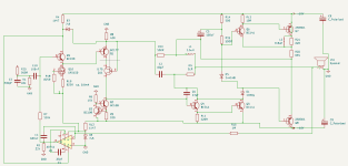
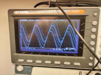
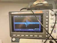
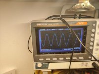
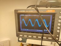
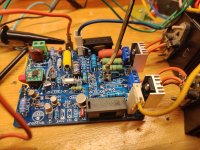
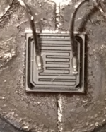
Those seemed to work fine too ,at least at 1kHz, nice full output of >15V in 8Ohm with a psu of +-27V , but at 5kHz it managed only 6V in 8 Ohm and at 20kHz 2V was the max. Very disappointed, no 2SB361 anymore and the AUY27 I had was crapola, two days of building ,testing and fault finding for nothing more than John with the short surname. But, inversing the circuit from NPN to PNP dumpers works fine. I tried with a few MJ2955 of chinese origin and they performed reasonably well up to 20kHz , but with max. output of 12.5V in 8Ohm , not the 15.7V at 1kHz into 8Ohm. Attached the schematic as it currently is , with a few (scope) foto's . I have parasatanical oscillations at around 14MHz, even when shut off I see weird ringing on the oscilloscope , foto number 5. foto 2 is the board, the dumpers are hanging from the orange wires at the right with their own small heatsinks, foto 3 and 6 are the oscillations at around 14MHz , foto 5 is the ringing if the board is shut off, foto 4 is the output at 1kHz with the AUY27 dumpers. Foto 1 is the currently used circuit schematic, but not with the 2SB361, sigh, but with the AUY27. Not the outcome I hoped for, still don't understand what I did with those 2SB361 transistors. I don't have the means or knowedge to analyse where the auy27 go wrong at higher freguencies, but I think they are not up to the task of driving the bridge at those frequencies. 2V in 8 Ohm is what the class A stage manages on it's own, without dumpers. As allso the MJ2955 stops at 12.5V in 8 ohm , there maybe more at fault .
I changed the circuit to a 306 lookalike, but there is sufficient difference to suspect inadequacies in the driver stages. The set boards (of different make though, bigger single sided boards) with the same circuit layout, a sort of simple quad 306 design, with 2SA1668 class A stage and 2SD718 dumpers works flawlessly and sounds really good too, something which made me reconsider my Taylor T20 base SET amp. Quad current dump technologie is just as fascinating as tube amps.
Attachments
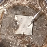
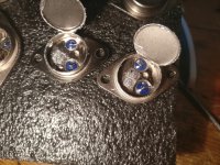
Today tested the board with 2sa1065 , Ft 50MHz multi emitter, and that worked flawlessly, 15.4V in 8 Ohm, over the whole audio band. Attached close up of a blown 2sa1065 where one can see clearly the multi emitter structure, compared to a philips BDY90, Ft 70MHz and last picure isc semi mj15003 ,Ft2MHz and 2sd551. The 2sd551 is supposed to have an Ft of 15MHz , to reach that Ft isc semi used two smaller dies in one enclosure. The MJ2955 was allso isc semi product.
As the 2sa1065 performed flawlessly with the circuit, I experimented further with the AUY27 and by increasing the class A stage current more towards the original Quad 405 quiescent current of 50mA by replacing the two 560 Ohm resistors with two 330Ohm, I got the AUY27 to perform better, now at 10kHz I got 12V output and at 20kHz still 6.5V.
The germanium transistors don't like constant tone tests at full power at the higher frequancies of 10-20kHz. They get extremely hot than and I measured them while they were that hot, and one had turned into a J-Fet with Ugs of 66V and the other a very low Hfe of 4 transistor. After cooling down they both measured again as original, Hfe 50 and Vbe ca. 90mV. Reading up on germanium detoriation , it seems that ge transistors are far more symmetrical than silicon, and CE reverse connected seemed to give sometimes an allmost equal Hfe as normal connection. At one point that seemed to have been used to reformat the pn juntions again in the case of excessive leakage which germanium seems to suffer from. All in all, not recommended for actual use. I connected today this board to one channel and the normal quad 405 board to the other channel of my preamp and listening test didn't reveal any difference between the two. On noirmal listening levels, the germanium transistors stay just as cool as the 2sd718 used in the normal boards .
Attachments
- Home
- Amplifiers
- Solid State
- QUAD 305 question