My QUAD 303 was shelved under normal room conditions for 10 years, and it was working flawlessly then.
Today, I connected it again to my 34 preamp, and a set of speakers.
Surprisingly, one channel has developed a constant noise, very audible, like pink noise with only high frequencies. Not crackling noise, not motorboating.
Noise level is independent from volume, even with no preamp, the noise is the same.
I had replaced the filter electrolytics, output electrolytics and electrolytics on the amplifier boards already back in 2000, and used high grade Philips/BC electrolytics (light blue ones). As said, the 303 worked perfectly until I shelved it around 2010.
Today I opened it up and tested rail voltage, half rail voltage, bias and DC setpoints of the transistors. (Un-) fortunately, all seem to be OK.
All capacitors on the boards looked OK too.
With my scope I can trace the noise all the way back to the collector of TR102. Everything "before" that, is clean, including the base of TR102.
Noise level on the speaker terminals is approx 100 mV (tt)
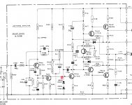
Full schematic can be found here: http://www.meridian-audio.info/public/quad-303-service-data[1961].pdf. I have the "newer than 11500 version".
I could use some guidance to test further, or tips/hints (faulty ceramic cap? noisy resistor?). I know the output triplets can be sensitive to oscillation, but I never changed any transistor, and the noise seems a broad spectrum noise....
I will be off-line during Christmas, but after that I have time to test a little more. TIA!
Today, I connected it again to my 34 preamp, and a set of speakers.
Surprisingly, one channel has developed a constant noise, very audible, like pink noise with only high frequencies. Not crackling noise, not motorboating.
Noise level is independent from volume, even with no preamp, the noise is the same.
I had replaced the filter electrolytics, output electrolytics and electrolytics on the amplifier boards already back in 2000, and used high grade Philips/BC electrolytics (light blue ones). As said, the 303 worked perfectly until I shelved it around 2010.
Today I opened it up and tested rail voltage, half rail voltage, bias and DC setpoints of the transistors. (Un-) fortunately, all seem to be OK.
All capacitors on the boards looked OK too.
With my scope I can trace the noise all the way back to the collector of TR102. Everything "before" that, is clean, including the base of TR102.
Noise level on the speaker terminals is approx 100 mV (tt)
Full schematic can be found here: http://www.meridian-audio.info/public/quad-303-service-data[1961].pdf. I have the "newer than 11500 version".
I could use some guidance to test further, or tips/hints (faulty ceramic cap? noisy resistor?). I know the output triplets can be sensitive to oscillation, but I never changed any transistor, and the noise seems a broad spectrum noise....
I will be off-line during Christmas, but after that I have time to test a little more. TIA!
Attachments
Working backwards from the output, TR102 is the first stage with voltage gain, so it is logical that the noise level at TR102's base is much smaller than at its collector and that the level at its collector is more or less the same as at the amplifier output. That still holds when the noise is not generated by TR102.
Noise of the input stage is not suppressed by feedback, so my guess would be that the cause is somewhere in the vicinity of the input stage or in the feedback network. I can't be more specific than that, unfortunately.
Regarding rayma's hypothesis, if your scope has a bandwidth of a few hundreds of megahertz, you could take a 1:1 passive probe, connect the probe tip to the ground lead and use the whole thing as a loop antenna that you can move around in the amplifier trying to locate oscillating transistors. Regarding mjf's hypothesis, RV100 would seem to be the trimpot most likely to cause it, even though C104 is supposed to prevent that.
I spent a few minutes (still Christmas here...) on the 303 noisy channel:
- replaced input cap: no difference. Shorting input also yields no difference.
- measured all resistors: all within tolerance.
- checked C104 and C106: all good.
Hopefully I will continue tomorrow.
- replaced input cap: no difference. Shorting input also yields no difference.
- measured all resistors: all within tolerance.
- checked C104 and C106: all good.
Hopefully I will continue tomorrow.
Did you ever apply an excessive input signal that might have caused emitter-base avalanche breakdown in TR100, and if so, was that on 24 December 2020?
You'd think the 22k feedback resistor would protect against that, but maybe not. Then there's also static discharge.
Not sure if you’re kidding about dec 24.... but no.🙂Did you ever apply an excessive input signal that might have caused emitter-base avalanche breakdown in TR100, and if so, was that on 24 December 2020?
I tested with my known good 34. And after that without input connected.
Will check whether I have suitable replacements for Tr100-102.
Thx again!
Last edited:
Thx, I assumed r100 provides a reasonable low input impedance, although 220k could indeed be a bit high in that respect.
You'd think the 22k feedback resistor would protect against that, but maybe not. Then there's also static discharge.
Do you mean the 22 kohm between the input and TR100? Good point, that would limit the current and slow down the degradation.
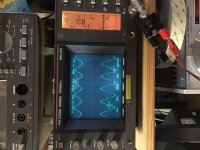
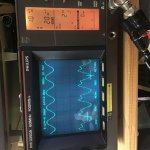
I tested some more with a 250 Hz sine wave input (trace A, 15mV tt).
The output is trace B, with a 10:1 probe measured on p5 in the schematic. The distortion is quite audible.
Pic1: no load.
Pic2: speaker load.
Looks like that under load, the upper half of the sine wave distorts.
I can set bias and half-dc rail correctly.
The output is trace B, with a 10:1 probe measured on p5 in the schematic. The distortion is quite audible.
Pic1: no load.
Pic2: speaker load.
Looks like that under load, the upper half of the sine wave distorts.
I can set bias and half-dc rail correctly.
Attachments
During the work the collector of Tr1 was indeed disconnected from the pcb...After reconnecting it the amp seem to behave as before (I.e. with the problem).Did an output transistor get disconnected, changing the triplet into a Sziklai pair?
As said, I can set bias and half-rail correctly.
BTW: thanks for looking into this!
I started this thread because I heard and measured noise in one channel, without applying an input signal. I did therefore not see a distorted output sine.With both problems, noise and distortion, or with only the noise this thread started with?
Today, I applied a sine wave and saw and heard a distorted output.
After that Tr1 collector got loose. When reconnected, the distortion looked and sounded the same. The noise (at zero input) is still there.
Bias and mid-rail were, and are, still correctly set.
Were the other terminals of TR1 connected and does TR1 seem to behave normally when tested with a diode test function of a multimeter? Is TR105 also OK?
A disconnected collector of TR1 could cause a distortion similar to what you had, but you have it with or without disconnected TR1 collector. Interesting...
A disconnected collector of TR1 could cause a distortion similar to what you had, but you have it with or without disconnected TR1 collector. Interesting...
I’m afraid I screwed up big time: collector ot Tr1 was not connected properly (wire to pin 2 on the board). The eyelet was intermittently connected to the traces on the pcb.
Fixed this, and at first the amp seems to work! Up to undistorted 4 V rms into a 10E resistive load. Which is not even 2 Watts, but it looked clean.
However, bias is now extremely high (750 mA) and cannot set any lower! Looks like it’s working in class A 😡
I see a complete, undistorted sine (up to 4 V), so the output transistors are OK?
Perhaps I blew a driver?
Due to family issues I will not be able to work on the amp before Wednesday. And give it a good thought before I mess up things.....
Thanks again!
- Home
- Amplifiers
- Solid State
- QUAD 303 sudden noise in 1 channel