Hello Everyone
This is my first time posting here, and just wanted to say i am glad to be part of a great community of people with such skill in this area.")
Very recently my Quad 303 power amp has developed an issue with its left channel, i have definitely narrowed it down to the power amp after swapping cables and speakers. The channel has suddenly become extremely distorted and quite (barely audible, however base seems to make it through the most).
I inherited the quad 303 and 33 a few years ago from my grandfather who is a hifi nut. "I seem to have caught the same bug!" And out of the many amps i have, i just cant get over the quality of this amp. Sadly my grandfather still has possession of 4 matching Electrostatics.
I was wondering if anyone would know where the best place to start looking? I am currently studying a course in Avionics and want my future career to be in electronic maintenance. So i do have some knowledge and definitely not afraid to learn. Look forward to hearing from you,
Kind Regards
Bradley Fechner
This is my first time posting here, and just wanted to say i am glad to be part of a great community of people with such skill in this area.
Very recently my Quad 303 power amp has developed an issue with its left channel, i have definitely narrowed it down to the power amp after swapping cables and speakers. The channel has suddenly become extremely distorted and quite (barely audible, however base seems to make it through the most).
I inherited the quad 303 and 33 a few years ago from my grandfather who is a hifi nut. "I seem to have caught the same bug!
" And out of the many amps i have, i just cant get over the quality of this amp. Sadly my grandfather still has possession of 4 matching Electrostatics.I was wondering if anyone would know where the best place to start looking? I am currently studying a course in Avionics and want my future career to be in electronic maintenance. So i do have some knowledge and definitely not afraid to learn. Look forward to hearing from you,
Kind Regards
Bradley Fechner
On something that age the first thoughts have to be toward failing electrolytic capacitors.
One basic thing to check first to get an idea of what is happening. First connect your meter to the positive side of the speaker coupling cap and just leave it monitoring the voltage. It should be around one half of the supply voltage, so around 30 to 35 volts. Now see if that voltage changes drastically when the distortion sets in.
Its always good to try and find the exact cause of a problem rather than just change a load of parts in hope... even if the caps will need replacing at some point... its still best to fix the fault first. The DC check will give an idea of what type of fault this is.
And welcome to diyAudio
Hello Mooly
Thank you very much, i also suspected these and sure enough i think we found our problem!
the left channel coupling capacitor only measures 1.5V as the distortion is instant and it very very slowly rises. Testing the right channel coupling capacitor gives me the 30 volts.
So would i be right in saying, that the capacitors dielectric has broken down and is leaking very badly allowing dc current to the speaker which increasing the distortion? This really enforces what i was learning about the use of coupling capacitors in amplifiers just only last week
It almost certainly isn't the speaker coupling cap because if it were then the current flow required to pull the voltage that low would be frying the speaker and frying the output transistors. That was a key voltage that shows the problem is DC rather than a purely AC fault. It could still be a leaky cap elsewhere though.
Now there were a couple of different versions of the 303 with minor differences to certain parts of the circuit but the basic procedure is the same.
So, just to eliminate catastrophic failure of the output stage we should measure the two 0.3 ohm emitter resistors that connect to the output transistors. Just make sure they are not open circuit. Beyond that, all the evidence should be there in the form of the voltage readings at various points in the circuit.
Key test voltages are,
1/ The base of TR103
2/ The voltage ACROSS R114
3/ The voltage on the emitter of TR100
Hi Bradley
Welcome to the forum, the 303 is quite a classic, and partnered with ESL57s
just about perfect. Other speakers that sound good are the early AR's like AR7's
The 33 these days sadly is a door stop but can be transformed or morphed into
a LDR preamp, the boards I manufacture fit perfectly. You then get the
classic Quad look and excellent audio ability.
Check that the regulator is working, you should measure 67 volts
approx 33v then on the amp side of each channel of the coupling cap.
Also check R115 as being 2.2 ohms.
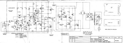
Schematic attached
Cheers / Chris
Welcome to the forum, the 303 is quite a classic, and partnered with ESL57s
just about perfect. Other speakers that sound good are the early AR's like AR7's
The 33 these days sadly is a door stop but can be transformed or morphed into
a LDR preamp, the boards I manufacture fit perfectly. You then get the
classic Quad look and excellent audio ability.
Check that the regulator is working, you should measure 67 volts
approx 33v then on the amp side of each channel of the coupling cap.
Also check R115 as being 2.2 ohms.
Schematic attached
Cheers / Chris
Attachments
It almost certainly isn't the speaker coupling cap because if it were then the current flow required to pull the voltage that low would be frying the speaker and frying the output transistors.
That makes sense, so the voltage drop must be before the coupling cap.
So, just to eliminate catastrophic failure of the output stage we should measure the two 0.3 ohm emitter resistors that connect to the output transistors.
The 0.3 Ohm resistors both measure ok, so thankfully good here.
Key test voltages are,
1/ The base of TR103
2/ The voltage ACROSS R114
3/ The voltage on the emitter of TR100
I found a copy of the 303 service data sheets and a schematic and i can see the voltage across C101 should be 9V (same measurement as voltage on the emitter of TR100). These were the voltages i measured at those test points:
1. TR103 Base Voltage 2.2V
2. R114 Voltage drop 0.707V
3. TR100 Emitter Voltage 2.1V
In contrast, i measured the same points on the right amplifier board, giving me:
1. TR103 Base Voltage 29V
2. R114 Voltage drop 0.4V
3. TR100 Emitter Voltage 7.1V
Hi Bradley
Welcome to the forum, the 303 is quite a classic, and partnered with ESL57s
just about perfect. Other speakers that sound good are the early AR's like AR7's
Hello Chris
I certainly enjoy listening to my Grandfathers set up of ESL57's, he has 4 (2 stacked up either side on custom made stands originally done by quad when they were bought new. they can certainly blast you away
I understand as 'Bare' said there are better amps. I worked in a small business high-end audio shop for a couple of years and they certainly still make some great sounding amps today, i especially like the valves.
Check that the regulator is working, you should measure 67 volts
approx 33v then on the amp side of each channel of the coupling cap.
Also check R115 as being 2.2 ohms.
The Regulator indeed gives me the correct 67V and as i found before, the left channel coupling capacitor indeed only reads 1.5v compared to the 30V on the right channel. R115 on both amp boards measures a 1.5 ohms, is this ok?
Hmmm... not as drastically amiss as I thought they might be. No matter...
R114 volt drop is a little odd. Can you recheck that and also measure the voltage across the two series connected diodes MR100 and MR101.
Is your amp the version with TR107 fitted or the version with the diode bias network fitted ?
R114 volt drop is a little odd. Can you recheck that and also measure the voltage across the two series connected diodes MR100 and MR101.
Is your amp the version with TR107 fitted or the version with the diode bias network fitted ?
A bit more for you to work on and check. The problem for fault finding on any amp is that the whole amp is a loop, that loop being closed by the action of negative feedback. That means that any basic symptom could have many possible causes. Initially we have to try and determine the cause with as little intervention as possible.
The voltage on the output cap is low because the output stage is not being turned on. The voltage at TR103 base needs to also be around 30-35 volts.
Possible causes.
There could be a problem with the chain R116, R117 (and if fitted) RV101.
TR102 could be being turned hard on which would pull the output stage voltage down. From the reading of 0.7 volts across R114 this appears to be happening.
Possible causes for that scenario...
C105 could be leaky. The only way to prove is to isolate one end of it and measure on a high ohms range. To power the amp up with it removed is risky because it could make the whole thing oscillate. Even then its not definitive unless you are 100% sure of the meter and its ability to measure in the high meg ohms region. Substitution is the answer in that case.
TR101 could be turned OFF. This is easily checked by measuring the base/emitter volts (that's across B and E) and also the voltage across R109. If there is zero volts across R109 then its off. The B/E volt drop should be in the 0.6 volt region.
C101 could be leaky. That would be dropping the first stage supply voltage.
C102 could be leaky. That would just keep TR101 held off.
Something like the above are probably the most likely suspects at this stage.
In fact any of the smaller non electrolytic caps could have developed a leakage. The best way to check these is just to quickly isolate one lead (use solder braid for a quick clean removal).
Just happen to be learning about negative feedback in oppamps last week aswell , they were covered in my last exam that i didn’t do so well in. I have a general idea how it works but they still baffle me a bit.
So firstly my amp is the version with the fitted TR107, with serial number of 66745 (I believe the revision was produced from serial number 11500).
These are the some measurements i have taken, some extras i took may or may not be of interest, I have highlighted measurements you mentioned and ones that showed significant differences between left and right Amplifier boards;
Left Hand Channel
MR100 Voltage Drop 0.704v
MR101 Voltage Drop 0.702v
TR101 Base/Emitter voltage drop 0.608v
TR102 Base Voltage 1.4v
R102 Voltage Drop 2v
R104 Voltage Drop 67.5v
R105 Voltage Drop 1.3v
R106 Voltage Drop 0v
R107 Voltage Drop 0.66v
R108 Voltage Drop 0.849v
R109 Voltage Drop 0.072v
R110 Voltage Drop 0.42v
R111 Voltage Drop 0.1v
R112 Voltage Drop 68.3v
R113 Voltage Drop 0.95v
R114 Voltage Drop 0.72v
R116 Voltage Drop 33
R117 Voltage Drop 33v
R122 Voltage Drop 0.035v
R130 Voltage Drop 68.9v
Right Hand Channel
MR100 Voltage Drop 0.51v
MR101 Voltage Drop 0.528v
TR101 Base/Emitter voltage drop 0.63v
TR102 Base Voltage 1.03v
R102 Voltage Drop 7.81v
R104 Voltage Drop 62.3v
R105 Voltage Drop 1.7v
R106 Voltage Drop 0v
R107 Voltage Drop 0.8v
R108 Voltage Drop 0.02v
R109 Voltage Drop 0.174v
R110 voltage drop 4.5v
R111 Voltage drop 0.4v
R112 Voltage Drop 68.7v
R113 Voltage Drop 22.78v
R114 Voltage drop 0.43v
R116 Voltage Drop 19v
R117 Voltage Drop 19v
R122 Voltage Drop 0.6v
R130 Voltage Drop 63.4v
Regulator Board
R200 Voltage Drop 41v
R201 Voltage Drop 40v
R202 Voltage Drop 43v
R203 Voltage Drop 11.4v
R204 Voltage Drop 57.7v
R205 Voltage Drop 1.14v
R206 Voltage Drop 0.077v
R207 Voltage Drop 0.5v
MR200 Voltage Drop 15v
MR201 Voltage Drop 12v
RV200 Voltage Drop 14.8v
Test point On schematic at R111 says should read approx. 8.5v
Voltage test point at R111 0.64v on Left
Voltage test point at R111 6.5v on Right
I haven't tested any caps, as i am unsure whats going on when isolate them like that, and i would like to do as least soldering to the board as possible. hopefully some of the above measurements may shed some new light.
, they were covered in my last exam that i didn’t do so well in. I have a general idea how it works but they still baffle me a bit.So firstly my amp is the version with the fitted TR107, with serial number of 66745 (I believe the revision was produced from serial number 11500).
These are the some measurements i have taken, some extras i took may or may not be of interest, I have highlighted measurements you mentioned and ones that showed significant differences between left and right Amplifier boards;
Left Hand Channel
MR100 Voltage Drop 0.704v
MR101 Voltage Drop 0.702v
TR101 Base/Emitter voltage drop 0.608v
TR102 Base Voltage 1.4v
R102 Voltage Drop 2v
R104 Voltage Drop 67.5v
R105 Voltage Drop 1.3v
R106 Voltage Drop 0v
R107 Voltage Drop 0.66v
R108 Voltage Drop 0.849v
R109 Voltage Drop 0.072v
R110 Voltage Drop 0.42v
R111 Voltage Drop 0.1v
R112 Voltage Drop 68.3v
R113 Voltage Drop 0.95v
R114 Voltage Drop 0.72v
R116 Voltage Drop 33
R117 Voltage Drop 33v
R122 Voltage Drop 0.035v
R130 Voltage Drop 68.9v
Right Hand Channel
MR100 Voltage Drop 0.51v
MR101 Voltage Drop 0.528v
TR101 Base/Emitter voltage drop 0.63v
TR102 Base Voltage 1.03v
R102 Voltage Drop 7.81v
R104 Voltage Drop 62.3v
R105 Voltage Drop 1.7v
R106 Voltage Drop 0v
R107 Voltage Drop 0.8v
R108 Voltage Drop 0.02v
R109 Voltage Drop 0.174v
R110 voltage drop 4.5v
R111 Voltage drop 0.4v
R112 Voltage Drop 68.7v
R113 Voltage Drop 22.78v
R114 Voltage drop 0.43v
R116 Voltage Drop 19v
R117 Voltage Drop 19v
R122 Voltage Drop 0.6v
R130 Voltage Drop 63.4v
Regulator Board
R200 Voltage Drop 41v
R201 Voltage Drop 40v
R202 Voltage Drop 43v
R203 Voltage Drop 11.4v
R204 Voltage Drop 57.7v
R205 Voltage Drop 1.14v
R206 Voltage Drop 0.077v
R207 Voltage Drop 0.5v
MR200 Voltage Drop 15v
MR201 Voltage Drop 12v
RV200 Voltage Drop 14.8v
Test point On schematic at R111 says should read approx. 8.5v
Voltage test point at R111 0.64v on Left
Voltage test point at R111 6.5v on Right
I haven't tested any caps, as i am unsure whats going on when isolate them like that, and i would like to do as least soldering to the board as possible. hopefully some of the above measurements may shed some new light.
Sorry for the late reply.
Well those are pretty comprehensive measurements and they tell us that TR101 appears to be OFF. R109 has essentially no current flowing and so T103 is fully ON. The slightly higher volt drop across MR100 and MR101 also tend to confirm that.
I'm going to go for two possible problems. Check first that R104 is OK at 22k. You must read it with one end isolated in order to get a true reading. If that is OK then C101 looks suspect. The only way to check that is by removing it and substituting. The value isn't critical, anything from 100uf to 1000uf would be OK as a test. Obviously check it for leakage on your meter but with electros it can be a bit tricky to interpret the results. For a DVM you need the red lead on the plus end of the cap to maintain polarity under test( and cap out of circuit).
See what find with those first.
Well those are pretty comprehensive measurements
and they tell us that TR101 appears to be OFF. R109 has essentially no current flowing and so T103 is fully ON. The slightly higher volt drop across MR100 and MR101 also tend to confirm that.I'm going to go for two possible problems. Check first that R104 is OK at 22k. You must read it with one end isolated in order to get a true reading. If that is OK then C101 looks suspect. The only way to check that is by removing it and substituting. The value isn't critical, anything from 100uf to 1000uf would be OK as a test. Obviously check it for leakage on your meter but with electros it can be a bit tricky to interpret the results. For a DVM you need the red lead on the plus end of the cap to maintain polarity under test( and cap out of circuit).
See what find with those first.
Some interesting results and a step closer, i found that R104 on the left channel board measured 83K ohms, replacing this with a new 22K ohm resistor gave some mixed results, fixing some values and throwing some value way out of line.
9 volts now appears on the emitter leg of TR100 and R109 voltage has risen to a similar voltage to R109 of the right hand channel. But the left channel coupling cap voltage is no 62V! almost rail voltage.
Red highlights show there is a difference in values and Blue shows a very significant difference in values.
Right Channel Coupling Cap 24.8V
Left Channel Coupling Cap 62v (almost rail voltage!)
Left Hand Channel
MR100 Voltage Drop 0.3v
MR101 Voltage Drop 0.3v
TR101 Base/Emitter voltage drop 0.63v
TR102 Base Voltage 0.64v
TR103 Base Voltage 64v
R102 Voltage Drop 9.18v
R104 Voltage Drop 59.7v
R105 Voltage Drop 1.6v
R107 Voltage Drop 0.8v
R108 Voltage Drop 0.02v
R109 Voltage Drop 0.16v
R110 Voltage Drop 5.3v
R111 Voltage Drop 0.46v
R112 Voltage Drop 68.3v
R113 Voltage Drop 55v
R114 Voltage Drop 0.04v
R116 Voltage Drop 2v
R117 Voltage Drop 2v
R130 Voltage Drop 61.3v
Right Hand Channel
MR100 Voltage Drop 0.51v
MR101 Voltage Drop 0.528v
TR101 Base/Emitter voltage drop 0.63v
TR102 Base Voltage 1.08v
TR103 Base Voltage 25v
R102 Voltage Drop 7.81v
R104 Voltage Drop 62.8
R105 Voltage Drop 1.7v
R107 Voltage Drop 0.8v
R108 Voltage Drop 0.02v
R109 Voltage Drop 0.174v
R110 voltage drop 4.3v
R111 Voltage drop 0.38v
R112 Voltage Drop 68.7v
R113 Voltage Drop 19v
R114 Voltage drop 0.43v
R116 Voltage Drop 21v
R117 Voltage Drop 21v
R130 Voltage Drop 62.8v
A bit more for you to go on...
Its worth also checking the other high value resistors R130 and R112 in the same way. With the previous fault R112 will have been subject to the full rail voltage. If the Quad uses old carbon or carbon composition type resistors then those two are worth checking.
Its worth also checking the other high value resistors R130 and R112 in the same way. With the previous fault R112 will have been subject to the full rail voltage. If the Quad uses old carbon or carbon composition type resistors then those two are worth checking.
Right on the money my friend!!
R130 measured open! replacing it brought all the voltages to spec. Changing RV100 brought it back in line with right channel. And in testing it, sounds just as good as it did before, very glad to be able to listen to my music on this amp once again.
Thankyou very much for your help Mooly, i wish i was able to work next to someone like you to gain the skill of repair. All in good time
Kind Regards
Bradley Fechner
Quad 303 Power Amplifier - Both Channels Distorted
Hi guys,
I have built the amplifier based on the original diagram, with just a few component replacements – MR100/1 and MR105/6 are 1N4148 and Tr105 and Tr106 are respectively 2N5322 and 2N5320. There is significant distortion even at low levels (both channels).
I also have a problem with the quiescent current adjustment – no matter what the position of RV101 is, the ampere meter reads 0mA. I have stable 67V from the PSU, solid 33,5V at the output. All components are new, the distortion is present from the very moment I “brought to live” both boards.
Thanks in advance for you suggestions and ideas!
First check is to measure the voltage across TR7 (vbe multiplier) and see what range is available as you alter the bias preset.
You need at least 1.5 volts and higher in order to be able to get the correct quiescent current.
That has to be a first step before looking deeper.
You need at least 1.5 volts and higher in order to be able to get the correct quiescent current.
That has to be a first step before looking deeper.
Hello Mooly,
Thanks for your prompt response.
I have managed to measure Ube=635mV of tr107. However when I attempted to measure collector-emitter voltage I heard short loud sound from the speaker (input grounded) and dark smoke raised from the PSU board. I think there is some damage on the amp board, as well. As soon as I obtain replacement parts and repair the damages will report on the results.
- Status
- This old topic is closed. If you want to reopen this topic, contact a moderator using the "Report Post" button.
- Home
- Amplifiers
- Solid State
- Quad 303 Power Amplifier - Left Channel Distorted