I'm aware that adding a series resistor to a woofer will alter its Qts. I've been using this calculator to see the effect it would have:
HiFi Loudspeaker Design
My question is when adding a single series resistor to multiple identical woofers, how am I supposed to calculate the effect on Qt. What should I be putting in for Qes and Qms?
HiFi Loudspeaker Design
My question is when adding a single series resistor to multiple identical woofers, how am I supposed to calculate the effect on Qt. What should I be putting in for Qes and Qms?
It depends upon how many (and how you wire) the identical woofers.
For example: If you have four woofers wired in a series/parallel arrangement it's just like having a single woofer.
Dave.
For example: If you have four woofers wired in a series/parallel arrangement it's just like having a single woofer.
Dave.
Thanks Dave. Just two in parallel with all shared crossover components. How do I calculate the change to Qt for both drivers then by adding a resistor in series to the crossover?
Last edited:
The impedance is only scaled. Whether series or parallel the impedance just doubles or halves. The Q stays the same. The output level also changes but this is irrelevant to your question about Q.
I understand what happens to impedance and I know each driver's Qt doesn't change when put in parallel, but that's not what I'm asking. To calculate new effective Qt with a series resistor, you need to know what the Qms, Qes, and Re is of one driver. When trying to calculate the effect of a series resistor on Qt of each driver, what values do I input into the calculator? Obviously the resistance halves, but does the Qes/Qms for the sake of the calculation stay the same? As per this page:
HiFi Loudspeaker Design
HiFi Loudspeaker Design
Whatever series resistor you calculate for one driver, halve it. This is the same as using the same Qms, Qes, half Re giving same before and after Qts. Or think of it this way, use the same single driver series resistor for each driver, two resistors, same end result.
Last edited:
One more question, if I may. If an L-Pad is applied to a woofer, I assume the series resistor has the same effect on Qts as if it were applied alone?
To calculate new effective Qt with a series resistor, you need to know what the Qms, Qes, and Re is of one driver. When trying to calculate the effect of a series resistor on Qt of each driver, what values do I input into the calculator?
Ideally you sum ALL the specs to create an average driver to design with.
GM
No, not this time. The parallel resistor will partially counteract the effect of the series resistor. Calculating extra series resistance is beyond the scope of the calculator, so..One more question, if I may. If an L-Pad is applied to a woofer, I assume the series resistor has the same effect on Qts as if it were applied alone?
If the resultant impedance is too high, or too variable to work with outside this part of the circuit, a parallel resistor (or series bandpass placed in parallel) can be placed before the series resistor, otherwise just use the one resistor on its own.
That's an interesting point Allen, and one which with my current insomnia-driven brain-haze I can't properly remember the theory behind. Series R will kick up Qe (and thereby Qt), but the shunt resistive element of an L-pad (or before) should counter this somewhat. How would you calculate the shift in these conditions? Daft question, but I'm not fit for much this morning. Granted, most people probably think that's a standard state for muggins here anyway... 😉
Probably the easiest way to visualise it in my mind would be that the smaller the parallel resistor, the closer to resistive the driver branch will look, and there will be zero frequency dependent effect when the series resistor simply divides with another resistor.
"Sum" the specs... What do you mean by sum? For two identical drivers behaving as one, none of the Q changes according to what others have told me here. Yes I know resistance and inductance is halved, but that's not what I've been asking about.Ideally you sum ALL the specs to create an average driver to design with.
GM
What GM is referring to is that drive units are never identical due to production tolerances &c. So when using multiple series / parallel units of the same type in a shared volume, you ideally should take the mean Qe, Qm, Re, Fs, Vas values, and use that for design purposes, because that is in effect what you're working with.
Last edited:
Gotcha, thanks again everyone.He means that drive units are never identical due to production tolerances &c. So when using multiple units of the same type in a shared volume, you take the mean Qe, Qm, Re, Fs, Vas etc. values, and use that for design purposes.
Indeed, GM and Scott are correct. Beyond this, there is more in what I was implying about impedance doubling. In the case of identical drivers in series, the varying impedances still share down to -6dB per driver at all frequencies, ie no change in Q.Yes I know resistance and inductance is halved, but that's not what I've been asking about.
With the many aspects of loudspeaker design, it is quite a good idea to break it into parts.
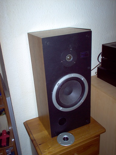
Bass response is quite interesting since the whole thing was put on a mathematical basis by Thiele-Small parameters. This is one of my closed-box speakers. 30L is usually about right for any 8" woofer. Whether you do 2nd order closed-box, 3rd order damped aperiodic or 4th order reflex depends on the exact bass unit.
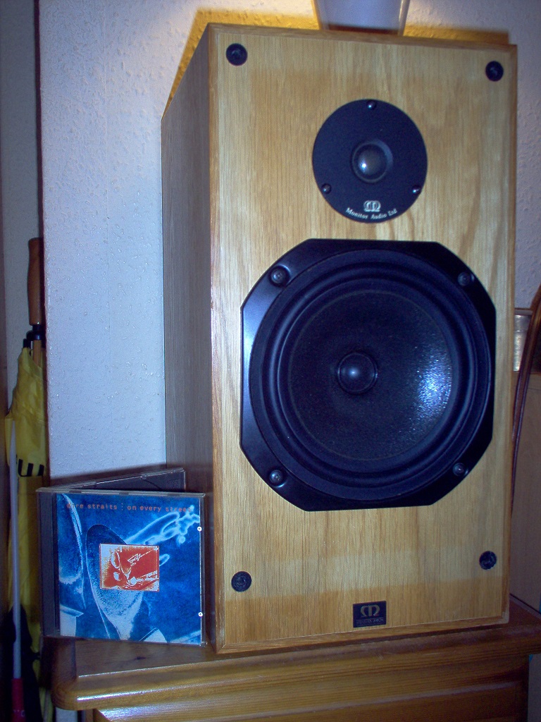
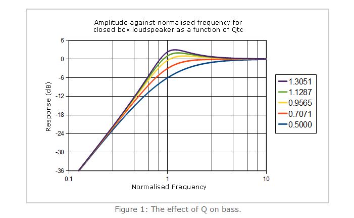
Thiele-Small determined that the main flat-baffle measurables of a bass driver are Qms, Qes, Qts. And Vas. Once you put it into a box, you get the Qtc, or cabinet response
If a small magnet driver has a Qts of 0.5, it is best in closed box of the measured Vas.
A big magnet driver of Qts 0.38 works best in reflex box of its measured Vas.
That's about it really. 😀
Questions then arise about what happens if you mess around with resistive damping. Whether from the amplifier's source impedance or physical resistors.
Exact calculations are here, in Morgan Jones' superb analysis:
Arpeggio Loudspeaker
You can use a simulator to try stuff for yourself:
Software | Visaton
I took a reflex Visaton W200S-8 woofer in 12L closed box with a solid state amplifier (The Solid Line), and added 6R at the front of the filter to see how it might respond with a valve SET amplifier of 6 ohm output impedance (The dotted line):

Ye Gods! It works for better deeper bass! A surprise. 😎
Bass response is quite interesting since the whole thing was put on a mathematical basis by Thiele-Small parameters. This is one of my closed-box speakers. 30L is usually about right for any 8" woofer. Whether you do 2nd order closed-box, 3rd order damped aperiodic or 4th order reflex depends on the exact bass unit.
Thiele-Small determined that the main flat-baffle measurables of a bass driver are Qms, Qes, Qts. And Vas. Once you put it into a box, you get the Qtc, or cabinet response
If a small magnet driver has a Qts of 0.5, it is best in closed box of the measured Vas.
A big magnet driver of Qts 0.38 works best in reflex box of its measured Vas.
That's about it really. 😀
Questions then arise about what happens if you mess around with resistive damping. Whether from the amplifier's source impedance or physical resistors.
Exact calculations are here, in Morgan Jones' superb analysis:
Arpeggio Loudspeaker
You can use a simulator to try stuff for yourself:
Software | Visaton
I took a reflex Visaton W200S-8 woofer in 12L closed box with a solid state amplifier (The Solid Line), and added 6R at the front of the filter to see how it might respond with a valve SET amplifier of 6 ohm output impedance (The dotted line):
Ye Gods! It works for better deeper bass! A surprise. 😎
That's one heck of an output impedance even by SET standards -most are in the 2.5ohm - 4ohm bracket, although higher does certainly happen. A few of the boxes I did for some of the MA drivers were done assuming similar conditions (smaller versions provided for voltage sources) & application notes explaining what they were for.
Be that as it may, this is exactly which series R, whether from wire, connections, components and / or amplifier output impedance should be factored into the box alignment if at all possible. The concomitant effect of a dedicated shunt resistive element on the box alignment is less well-known though, possibly because it's unusual and few of the popular lumped element box modelling software actually have the facility. Hence the reason muggins here had to ask Allen for a quick refresher (granted, being completely cream-crackered doesn't help, but needed anyway). BassBox has to a point; ditto Basta -from what you say Steve, it sounds like Boxsim allows it also? I don't have VituixCAD installed at present as I'm in the process of building up a new machine; I suspect it may.
Be that as it may, this is exactly which series R, whether from wire, connections, components and / or amplifier output impedance should be factored into the box alignment if at all possible. The concomitant effect of a dedicated shunt resistive element on the box alignment is less well-known though, possibly because it's unusual and few of the popular lumped element box modelling software actually have the facility. Hence the reason muggins here had to ask Allen for a quick refresher (granted, being completely cream-crackered doesn't help, but needed anyway). BassBox has to a point; ditto Basta -from what you say Steve, it sounds like Boxsim allows it also? I don't have VituixCAD installed at present as I'm in the process of building up a new machine; I suspect it may.
Last edited:
- Home
- Loudspeakers
- Multi-Way
- Qts with series resistor to multiple woofers