I did better yet, that jfet17 which is j112 can be swapped out for a higher listening gain jfet, n channel, providing the gate source drain nodes align to the mobo pinout. the operating tension is below one half of the rail 30, so this is about 16, thus a jfet n channel whose capacity for this tension differential would be ok. I don't know where the operating point is on the output versus input curve, but I can view in and out on the scope with an injected waveform. the purpose of doing this subst is to learn whether appreciable performance is gained by the higher gain (transconductance) Japanese jfet
Hi hewo,
I'd say you're into an area where the sound you get is completely personal choice. You are creating sound, so most of the worries of home audio do not apply. So, go make yourself happy with the sound you like best. Maybe even more distortion through the reverb box circuit.
-Chris
I don't think I suggested that. The trade-off would be distortion vs gain, and only to a certain point where gain might even decline due to excessive loading.Your idea of replacing that static 3k3 resistor with a micro trimmer say quarter watt 5k is merited.
JIS (2SK series) have a different pin out to JEDEC (North American 2N and J series). Often you can swap drain and source freely unless you start using more specialized J-FETs - like RF types for example. RF transistors often have breakdown voltages around 15 volts too.I did better yet, that jfet17 which is j112 can be swapped out for a higher listening gain jfet
I'd say you're into an area where the sound you get is completely personal choice. You are creating sound, so most of the worries of home audio do not apply. So, go make yourself happy with the sound you like best. Maybe even more distortion through the reverb box circuit.
-Chris
did not change fet17 yet nor 3k3 resistor yet.
instead output fet17 replaced 104 cap using 684 cap nonpolar
thats seven fold bigger capacitance, allowing furthered spectrum to squeeze thru the dwnstrm 47k and further dwnstrm 50k pot (reverb level), finally into earth
so we see the fet17 (listening) output drives thru apprx 100K into earth neglecting rail powering and degenerative crosstalk path
darn i should have measured fet17 in the tester while i had the mobo out yesterday installing said 684 cap as c37, fet17's output dc blocking. recall i delineated of the slight excursions noise with coax pinout reversal error. technically, the gigantic tank antenna metal created ambient noise signal continuously for fet17 to amplify, but we dont know if such ambient noise injured fet17 partially. the only way is to test it. usually the jfet transconductance reading gets worse, ive seen this over time usage esp in clipping soft applications purposefully
Hi hewo,
When you see a design that excludes some frequencies, there is probably a good reason why that was done. May as well try your changes since you have done this already. you won't break anything unless you really overdrive the spring unit.
-Chris
Reverb units do not normally run bass frequencies, only midrange. The bass will cause problems in what you normally want to hear. Try to keep the cutoff the same frequency if you can.thats seven fold bigger capacitance, allowing furthered spectrum to squeeze thru the dwnstrm 47k and further dwnstrm 50k pot (reverb level), finally into earth
When you see a design that excludes some frequencies, there is probably a good reason why that was done. May as well try your changes since you have done this already. you won't break anything unless you really overdrive the spring unit.
-Chris
reverb midrange preference
ok, did not hear much sonic change with the c37 684 bipolar cap.
so will revert back to 104 bipolar cap, tiny chicklet chewing gum rectanguloid 63wvdc, was this metalized polyester film heal'able puncture wounds, called punchthrough burns recoverable? did they even have this technology in the 80's?
the greater reverb is dialed, the more you will hear fiducial hum from the dc supply, inescapable. how much hum? scope shows this fiducial hum is below the injected guitar signal, apprx 5% of injected at max level reverb. now by mounting the tank far away from the hum intruding emissions, will this fiducial hum go away? or is this hum here because its fed by the coax cables soldered into the reverb circuit mobo? the only way is to listen with tank location changed. I don't know if the current location is optimal insofar as hum introduction. tank mounts inside the spectacularly spacious internal chassis tray floor, farthest from the pt, tank flange facing downwards to gravity pulling, tank electrically isolated from chassis tray by way of soft neoprene sponge weatherstripping designed to seal door jams, very tiny pieces sized as chicklet chewing gum, on four flanged corners. too much sponging acts to unisolate earthquake perturbations arising out of the pt anchored into the chassis tray similarly with soft sponge grommets speared thru by semi-lose british rivets not threaded fasteners.
the factory mounted the tank in the cab's basement without any deadening sock. I move the tank upstairs into the chassis. why? to shorten the long coaxial cables, and maybe reduce direct speaker concussions onto tank. realize with tank upstairs now, speaker concussions first impinge the external barrier called the chassis metal. this does shake this chassis, which in turn shakes the tank that's semi-isolated from vibrations owing to the sponge soundshort mounts. the optimal reverb sound is to position the tank away from the amp completely, as in setting it onto concrete floor. this reveals the best sound ever as ive tried it with all amps just to confirm truth.
I did find that high gain j112 japan substitute, called 2sk170 whose transconductance is twice that of genuine j112. if installed as fet17 the listening jfet, it will amplify significant amounts of spring. j112 and 2sk170 are both n channel. j112 can withstand greater amperes fed into its gate, but in this apply as fet17 listening, the amount of amperes entering into the gate 2sk170 is trivial
Hi hewo,
-Chris
Sort of and yes. "Self healing" refers to recovering from a short circuit where the current pulse from the short vaporizes the conductive material. The affected capacitor would undergo a decline in capacitance if this was a normal mode of operation. If the short hasn't much current, the capacitor would remain shorted until enough current could clear the short. Therefore, in some circuits the capacitor may short and remain in that condition.metalized polyester film heal'able puncture wounds, called punchthrough burns recoverable? did they even have this technology in the 80's?
Yes! and now you understand why it is commonly mounted on the floor of the case instead of up on the amplifier chassis.the optimal reverb sound is to position the tank away from the amp completely
Any current flowing through the gate is a circuit fault condition unless you are using the J-FET as a (very) good signal rectifier. So no worries as you know that the gate is reverse biased in normal operation. Go ahead and use the 2SK170 if you like it better. Just make certain you have the pin-out correct.j112 and 2sk170 are both n channel. j112 can withstand greater amperes fed into its gate
-Chris
reverb good to know
thanks for the replies on GTK (good to know)
I use to hand carry naked tube chassis and separate reverb tank to performances, fragile susceptibility for damage, as I am too poor to afford wooden cabinetry for the tube builds. but I learned the reverb is spectacular with tank set on concrete stage floor as no external vibrations thwarted the guitar dedicated oscillating springs.
I have an idea to isolate the tank upstairs: called mass spring dashpot
when you achieve the correct proportions, by solving the ode (ordinary differential equation) from proper excitation boundary conditions, the tank should become isolated from external excitation forces (chassis tray into pinpoint sponge high-heels, sponge then transmits excitation into tank flange metal, and hence into suspended carriage that pre-tensions springs and anchors endpoint transducers)
whilst the frequencies being dealt with are wide ranged, a good overall mass spring dashpot configuration should likely cover this spectrum. nobody tried it yet I believe, too much humbug experimenting, so to speak, termed "derived experimentally, or empirically".
thus just as the class A fet common source has both, a cathode bypass resistor in parallel with a tantalum electrolytic, the tank flange lip can be paralleled with a leaf spring to suit in conjunction with the neoprene sponge. additionally, the tank can be increased in mass by affixing a known mass (cant decrease mass, right?)
my road amp in this forum had its tank affixed to the underside of the chassis tray, externally, without any discussed sound-short mounts, and boy did the hum prevail when reverb level was dialed upwards. this is 70's technology.
my mark one (orig Santana type that can substitute fets for ecc83) utilizes cabinetry chassis sound short mounts. this way the glass bottles won't get obliterated from speaker driven concussions. yet its tank was in the cabinet's basement within a very tough naugahyde felted sock.
btw, forgot to mention silver mica 221 hi-bypass on both tramp channels levels (not gains). if installed to gains, strident, but on levels, wonderful coloration.
Hi hewo,
Maybe some dense but lossy foam might be a good solution. Adding mass to that assembly would improve the isolation and build up your muscles at the same time. That's a win-win! 🙂
-Chris
Ever check the cost on these wonderful devices? I really like dash pots, but using them on a reverb tank is a waste of good money. Older multi-track recorders used to use these on the tension arms. They were really good glass ones with an adjustment for the degree of damping. Complete overkill for your application.a good overall mass spring dashpot configuration should likely cover this spectrum. nobody tried it yet I believe
Maybe some dense but lossy foam might be a good solution. Adding mass to that assembly would improve the isolation and build up your muscles at the same time. That's a win-win! 🙂
-Chris
oh! ok, the lossy foam like high decibel ear plugs that do not lose their memory
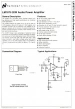
btw, viewing the schematic power amplifier, there is still that cold iron start up dc into voicecoil a mere quarter of a second, no harm no foul. is the mute capability of this IC able to eliminate this dc? I note that turning off the amp has no dc to voicecoil, and additionally if you re-power back up within minutes, the dc vanishes, meaning capacitor is still charged somewhere and has not bled down enough to result in dc fed to vc.
btw, viewing the schematic power amplifier, there is still that cold iron start up dc into voicecoil a mere quarter of a second, no harm no foul. is the mute capability of this IC able to eliminate this dc? I note that turning off the amp has no dc to voicecoil, and additionally if you re-power back up within minutes, the dc vanishes, meaning capacitor is still charged somewhere and has not bled down enough to result in dc fed to vc.
Hi hewo,
That chip does have a mute input pin (R9). You should look at the output of the amplifier on one channel and the mute input pin on the other channel. I am referring to a dual channel oscilloscope. It is possible that the mute circuit is almost working okay. Not working great, but sort of working. These problems can often be traced to a small timing capacitor that has degraded over time. Not unless the mute operation is a "feature" (small design flaw).
Normally a mute circuit detects the presence of the AC mains, but off the secondary of the power transformer. It is designed to go into mute instantly and time out for the release. When you turn the power off, the AC pulses disappear instantly (close enough) and the circuit mutes again. I don't see the actual muting circuit in that manual. Nice if you do have a muting problem that needs to be sorted.
-Chris
mute investigation
I will repost that ic spec attachment when I locate it.
The literature details if the mute pin is earthed no output whatsoever.
But schematic depicts mute pin engaged to other ic pins and components, and schematic could have editorials.
On this separate power amp pcb, I did overhaul all components except resistors (all fine), so the pivoting cap whose charge up and or discharge timing is reliable. Yet that quarter second cold iron startup still rings dc to vc. But again, once charged, if the power is turned off, then reenergized within a few minutes, the powerup is absent of any quarter second dc to vc.
So, this means gotta investigate two episodes with dual tracing to home into the reason why no dc to vc if cap retains sufficient stored charge.
There's also the possibility the ic is not what factory had long ago installed because of production era disparities. I have spares to swap and eval should this be last resort to cure dc.
Most of the time that speaker relay doesn't click, power amp output at no signal isn't zero volts, open relay coil, or some part for energize circuit bad. If regulator gets hot, measure it's output to see if right, and if not, find what is loading it down.
successful qinpu a3
It was bad electrolytic capacitor feeding tube warmup supervisory relay permissivity.
Fluke79 measures 5280uf yet labeled 470uf 16v,
Weird fluke 79 measures 1.3k ohms steady too, no failure displayed by 5280uf very misleading
It was bad electrolytic capacitor feeding tube warmup supervisory relay permissivity.
Fluke79 measures 5280uf yet labeled 470uf 16v,
Weird fluke 79 measures 1.3k ohms steady too, no failure displayed by 5280uf very misleading
late reply toxic encephalopathy
The encephalopathy is permanent, from chronic sewer gas, h2s, leached almagam hg, fugitives hg destroy blood brain cell boundary, impede o2 co2 glucose transport through cell wall, o2 starve means intox severe, stumbling unfocused literally not cognitive motor skills impaired
The worse part of expose to voc volcano tobacco vaporEcig combustion engine exhaust refineries stacks bbq and even radiative energies huge tv displays arrays, is the gi tract involuntarily wrything serpent peristaltic acceleration ejection of nutrients, hence tragic body mass plummet.
Hi hewo,
I'm very sorry to hear you have this problem. Would you mind if I asked which type? You do not have to answer if it makes you the least bit uncomfortable.
This may have scared your factory contact off. We'll do our best to understand your meaning in posts.
The pictures might be helpful. By chance, did you have a chance to measure the supply voltages and the DC offset voltages?
-Chris
The encephalopathy is permanent, from chronic sewer gas, h2s, leached almagam hg, fugitives hg destroy blood brain cell boundary, impede o2 co2 glucose transport through cell wall, o2 starve means intox severe, stumbling unfocused literally not cognitive motor skills impaired
The worse part of expose to voc volcano tobacco vaporEcig combustion engine exhaust refineries stacks bbq and even radiative energies huge tv displays arrays, is the gi tract involuntarily wrything serpent peristaltic acceleration ejection of nutrients, hence tragic body mass plummet.
Last edited by a moderator:
Hi hewo,
That has got to make living life tough. Being permanent tends to depress you, clinically. I hope you have support for that.
For this condition you are doing very well. Keep it up!
Best, Chris
That has got to make living life tough. Being permanent tends to depress you, clinically. I hope you have support for that.
For this condition you are doing very well. Keep it up!
Best, Chris
comparing others brings depression
Yes depressing comparing others unaffected by pollutes airborne delivered into lung and consequentual fate only I receive endangerment.
Kinda reminiscent of comic book superman exposure kryptonite. chronic pollute oppressed, poor fellow expires (deteriorates).
I need to get finances to live way up in the boonies. I hope I prevail in claiming employment injury finances to do so. Else I waste tortuously in congest pollutes of normal neighborhood suburb to metropolis severe congest. Deadly are the youth pollutes today, so powerful wicked impact central nervous system. Youth are plentiful and proximate in residential neighborhood because of land pricing honolulu, bloodlines cram their residence high density, and youth are bayed at home drugging out chronically, right next to me! They just don't stop, even thru the night, they don't sleep, how do they function without sleep? Police tell me drugs can disallow sleep, sheer madness here
Hi hewo,
That has got to make living life tough. Being permanent tends to depress you, clinically. I hope you have support for that.
For this condition you are doing very well. Keep it up!
Best, Chris
Yes depressing comparing others unaffected by pollutes airborne delivered into lung and consequentual fate only I receive endangerment.
Kinda reminiscent of comic book superman exposure kryptonite. chronic pollute oppressed, poor fellow expires (deteriorates).
I need to get finances to live way up in the boonies. I hope I prevail in claiming employment injury finances to do so. Else I waste tortuously in congest pollutes of normal neighborhood suburb to metropolis severe congest. Deadly are the youth pollutes today, so powerful wicked impact central nervous system. Youth are plentiful and proximate in residential neighborhood because of land pricing honolulu, bloodlines cram their residence high density, and youth are bayed at home drugging out chronically, right next to me! They just don't stop, even thru the night, they don't sleep, how do they function without sleep? Police tell me drugs can disallow sleep, sheer madness here
Hi Hewo,
Everyone who has a permanent disability is in the same boat. No hope for a fix or cure, and you can't do whatever everyone else does. All you can do is accept it, and live with it the best you can.
-Chris
Everyone who has a permanent disability is in the same boat. No hope for a fix or cure, and you can't do whatever everyone else does. All you can do is accept it, and live with it the best you can.
-Chris
qinpu dc heater one side dies strange
One side of stereo channel dies from absent dc heater energy 6n3.
This resulted from fluke79 probe tip unsheathed accidentally bumping the low leg of zener9v simultaneously with c9014 collector in millimeter distance proximity. The reason for probing voltage of the two zener9v was to verify zener functionality. These zeners are conjugate flipflops for relay permissivity to engage disengage. I discovered this after the relay actuated measuring zener "live" during the click actuation. There can be only one of two zeners that receives working voltage to dump. This cleaves two conditions apart, heating during nonpermissivity, and heating with permissivity. This was shown by probing the applied voltage presence continuously before and after the click (i.e., during the click), one zener equalizes whilst the other engages). This relay permissivity logic is not fully understood. There's sensory scouts (trace) feeling the plus minus rails 18vdc, the 6n3 conduction once fully heated, and complicated monitoring of poweramp ic (LM1875). There's a timer circuit countdown too that's thrown in this permissivity mixture of constituents.
I removed these components to double check functionality, none bad, none questionable, so returned to pcb.
Lost heater dc to only one side was owed to solder well severage on the ground pin of heater reg 7806, as the pcb mirrors heater dc traces on opposite sides of the dual sided pcb.
Both heaters were fine, until the probe shorting fiasco, so the compromised "well" must be attributed to prior well soldering (replace7806) butchering, and cold solder fracture to one side's ground heating supply during the probe fiasco (7806 fin substrate nudged? resultant cold solder fracture?)
Close inspection revealed entangled welling copper within the well. Solder melting and simultaneous suction from the proper side of well access entrained the copper foil in jetstream flush mounting said foil back onto its retaining wall of the well. Sucking the wrong side dislodges the foil interrupting well passthru conductivity.
Amp plays very nice, appealing, bookshelf speakers are two-way, ebay celing speakers purchased cheap but treasured sound because of plywood 3/4" closed back enclosures I constructed. The celing speakers are butyl surround and dynamic horn (tweet) via crossover. I connected signal from android mp3 file into qinpu, marvel!
I don't know how to arbitrarily dial qinpu level because android has level within and it has immense qinpu level change effect, regardless of qinpu level dialed (anywhere between 9am through 3pm).
Android has equalizer too, immense affect slider dials, too many factors in arriving at some desired sound achieve. There's no distortion either, not a hint.
Gotta get efficient speakers, crossovers are parasitic gluttons.
Then can achieve coloration just like guitar speakers.
- Status
- Not open for further replies.
- Home
- Amplifiers
- Solid State
- qinpu a3 doesn't relay click