Forgot big change informing:
Both channel tone stack slope resistors doubled in value to impede lower frequencies.
This would definitely weaken signal totalized energies fed to fet cascade 15&16 Driving tank.
Doubling 47k and 33k to 100k and 68k appreciably diminishes stack output energies but the result desired is emphatic pronounce sassy brit signature.
The aforementioned 105x35 tantalum of fet15 is called cathode bias bypass cap. Gotta test it out of circuit, but tant's rarely fault unless overranged and or polar reversal energy applied
Hi hewo,
Use a ground return. Most RCA connectors for that are isolated from the reverb unit casing. This is a low impedance drive to move the springs. Shielded wire is a waste in this application. What you absolutely do require is both the signal and common return lines. The last place you want the return current running is in the input circuit.
Changes in the tone stack mean you are doing too much at once. Too many variables. Just get the reverb spring assy properly wired up, two connections at each RCA connection.
-Chris
I do.I don't think 12" coaxial runs are choking signal transport, even at 32 wire size stranded of signal conductor.
Use a ground return. Most RCA connectors for that are isolated from the reverb unit casing. This is a low impedance drive to move the springs. Shielded wire is a waste in this application. What you absolutely do require is both the signal and common return lines. The last place you want the return current running is in the input circuit.
Changes in the tone stack mean you are doing too much at once. Too many variables. Just get the reverb spring assy properly wired up, two connections at each RCA connection.
-Chris
Oh my such confusion:
1) the term input can be assigned to tank or to mobo and verywell so, but entirely conjugate
2) if intended to tank, input is shaker
3) if intended to mobo, input is listening fet whose job is to amplify what it hears
I remeasured dc ohms of tank coils, input says 31.2 and output says 60.1, or is this backwards, yes, the red receptacle says output and is the larger dc ohms reading. The fluke79 short leads have banana plugs with threaded barrel wire bites, they work lose giving inconsistencies, maybe gotta solder wire to banana for longevity troublefree.
Got android pictures plenty of mobo and tank. Will return link posting, likely facebook public link.
Hi hewo,
Okay, consider each piece as a separate object. The "mobo", or main circuit board (mobo is a computer term that doesn't translate) has an output and input to and from the spring reverb unit. The spring reverb unit also has an input and output from its perspective. Its the same as a receiver having an input and output to and from a tape recorder. The output from the tape recorder goes to the input of the receiver. Please forget computer terminology as it only confuses people in this trade. You will be less confused if you use the terminology that we use.
You can upload pictures directly to our server. See "Go Advanced", then below the screen for writing you can see "Manage Attachments". Go there and follow the instructions. You will upload the files from your computer or device.
-Chris
... and you think you're confused!Oh my such confusion:
Okay, consider each piece as a separate object. The "mobo", or main circuit board (mobo is a computer term that doesn't translate) has an output and input to and from the spring reverb unit. The spring reverb unit also has an input and output from its perspective. Its the same as a receiver having an input and output to and from a tape recorder. The output from the tape recorder goes to the input of the receiver. Please forget computer terminology as it only confuses people in this trade. You will be less confused if you use the terminology that we use.
You can upload pictures directly to our server. See "Go Advanced", then below the screen for writing you can see "Manage Attachments". Go there and follow the instructions. You will upload the files from your computer or device.
-Chris
android samsung galaxy SIII shoots pics like uzi machine gun. gotta upload as zip ftp again then after your call delete ftp package zip
download tank.zip 40Mb pics:
ftp://cchftp1.honolulu.gov
account: cchftpuser
password: cchftpuser
delete site's tank.zip after you download
ftp://cchftp1.honolulu.gov
account: cchftpuser
password: cchftpuser
delete site's tank.zip after you download
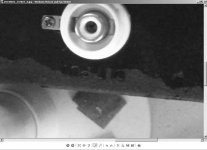
tank closeup
okay here is scoop:
1) red tank is input 60 ohm earth not to tank
2) white tank is output 30 ohm earth is to metal tank
3) core of white laminates labeled A600
4) core of red laminates labeled 800
so my prior writing of red being hotter identified as recovery side is WRONG!
its the opposite, the shaker transducer red is hotter labeled 800 for impedance?
Attachments
Are those jacks on / in and insulator?
What is the resistance from the center conductor to the outside of the RCA jacks?
What is the resistance from the center conductor to the outside of the RCA jacks?
Yup those red and white plastic rca female receptacles are floated onto metal but if you view red you'll see earth delivery by cabling never touches metal tank.
On the other side, you see the white having a metal finger fastened to tank metal, so this cable's earth does extend earth from mobo into tank metal acting as faraday cage minus.
I measured 30 and 60 dc ohms, for listening springs and shaking springs, quite unusual from norm whereby listening transducer has much hotter coil windings.
The dc ohm readings are true, I can probe the transducer coil wires directly should you believe the rca receptacles are parasitic corrosive leaking energies out to earth.
This tank should sound real good three springer!
whoops forgot to answer question of cabling run dc ohms, still have not swapped out cabling as directed to, owing to hazmat fiasco this morn at home. as you can see from the android photo's, the coaxial lengths are different, 16 inches shaker cabling and 12 inches listening cabling. the dc ohm is zero of either center conductor or braided shield, either cable. so this means 12" and 16" is permissible, but not for runs of 36" which is factory standard length. gotta set dials at nominal, inject frontend 22mvac_rms_1khz_sine and chk what's mvac level delivered across shaker transducer, what's mvac level generated by listening transducer. when you refer to the schematic, the rail energy is 30dcv throttled down by 471 resistor, so anticipate around 13 to 15vdc operating fet's_15&16. I don't know what level will be to shake spring nor do I know level generated by listening transducer.
don't worry of the tank's rca receptacles causing distress here. point to point, from mobo landings to transducer coil filament endpoint is zero ohms, whether coaxial center conductor or braided shield, and for both cables. so the rca receptacle is not culprit.
btw, I once disassembled a belton pan, to intentionally rewarp what I call bowing (just like guitar neck with truss rod). the trick is to precompensate the bowing so the carriage (which bows under spring tension) will align permanent magnet slugs centershot in the laminates aperture. what I realized was the magnets are culprit, they weaken over time I guess from continual excitation and equal and opposite counter excitation which likely ruins permanent magnetism. the poles of the magnets are diametrically opposed wrt spring axis. this makes it nearly impossible to rejuvenate permanent magnetism by contacting the slug with a powerful magnet learner.
tanks today cost over 20 to 30 dollars. this tramp is beyond giving up after all of the workhorse operations totalized.
Hi hewo,
Yes, a three spring reverb sound sound pretty rich.
You answered my questions. I wasn't worried about the RCA jacks, I wanted to know how you should be measuring instead of to the chassis. I think you were doing that. Anyway, measure from the RCA outside to the inner conductor. Forget measuring resistance with your new shielded wire. For the drive side it is too thin, period. You are transferring power to the spring actuator side.
Permanent magnets would more become weaker due to some serious jarring over a long time. They tend to become weaker simply due to age, but can be re-magnetized to full strength. The magnets would have to be removed from the assembly for that operation. I don't think they would be so weak that they wouldn't work. I still think the driving cable is too thin.
-Chris
Ok, this is what you're asking: unsolder the coils filament leads from the tanks rca receptacle. Do this for both coils.
Now measure resistance of all combinations between the red and white receptacles, crosstalking.
There should be absolutely no crosstalking. Why, because red receptacle is purely floating, delivering shaking electricity dedicated soley to shaking coil, and nowhere else.
Do this same crosstalk measurement schema of the unsoldered filament coils. Both coils are floated now so there should be absolutely no crosstalk.
However, doing this same crosstalk test on the two mobo cables will reveal crosstalk, why, earths of mobo adjoin braids shield of both cables, and hot signals are circuitry mixed per schematic, but with designed attempts for adequate isolation from each other (474 resistors block wet and dry signals crosstalk)
Hi hewo,
Do you have a schematic for this amplifier with the reverb unit installed?
No, please do not desolder anything! Once you unplug the connections you can measure the connectors. While both are unplugged, you shouldn't be reading any connections between the two "grounds" on the connectors. You probably will if the cables are connected to the amplifier.
-Chris
again schematic
Correct, w/ both cables disengaged from tank, rca earths are not connected, red/ white.
All ebay tanks have huge recoveries, like 2500 ohms listening coil.
Mine is 30ohms, says A600 on mylar yellow tape enveloping listening coil.
It would be illegal to throw 2500 impedance output of tank into A600 impedance receiving fet listening circuitry.
This means this tank is very oddballed!
Ok, I have fab'd 22gage teflon dual conductors, sheathed in braided shield, sheathed over in teflon jacketting. This will only be used on drive energy, to compare tank output energy, against the 32gage fancy.
Btw, photos reveal transducer laminations (called armature? Called core plates?) moderately rusty.
I recall saturating the rust using caig rejuvenator cleaner corrosion prevention spray, harmless. Radioshack lowered the price by half so I bought it for 15bucks. It fixed the pots real well, see schematic attached, 14pots
Attachments
Hi hewo,
Make certain you use as little cleaner as possible. It will destroy the protective lubricant on the carbon track. What goes noisy is the metallic slip ring - fingers connection, not the carbon track.
The terms you are using are non-standard and make it difficult for me to follow what you mean. I expect some misunderstanding between us. Please make a strong effort to use the lingo of this industry. For instance, the "rev" on the schematic stands for "reverb". I see R73 at 3K3. That will block almost all the power from the coil driving circuit. You can use a step down transformer to help - after R73! This will increase your levels a fair amount. Well, it should.
You need to use ohm's law so you can figure some of this stuff out for yourself. R73 is 3K3, or maybe 3,300 ohms might put this in perspective for you. You don't need to match power here, so exact impedance matching is not a critical thing.
-Chris
No, the 3k3 resistor is alright, because of the cascaded fet15&fet16, called j112, all seventeen fets were replaced with non- siliconix j112. Orig j112 all seventeen were siliconix 1980's era production.
Cascade amplification resembles Darlington principle I believe, to juice up horsepower to drive load.
I was just so anxious to hear the fet15/16 outcome, I still have not either swapped drive coaxial 22gage, and, take mvac readings off the two transducer coil filaments.
But the sound, all dials nominal (12 o'clock), is perfect, and reverb is very present full bodied.
The midrange must be attenuated, in lieu of 12 o'clock, either channel.
So, culprit was fet15/16 . I tested the suspects on the b&k tester, and their gm was scrawny, like 15, compared to new of 100.
But after retesting the suspects days afterwards again, mysteriously their gm returned 100.
So I don't believe these suspects are bad now, because there's no such thing as "self healing" once the channel gets injured.
How did these suspects get injured?
The gross mistake of soldering the fancy 32gage coaxials with their mobo pinouts flipped results in the following : the drive energy still affords shaking springs, because drive coil will still be fed ac into coil, except that braid of drive coax is hot and will pickup lots of surface area antenna emi. And I did hear hum, not bothersome, at that time of error pinouts. The recovery coax in pinout reversal blatantly excites the tank metal housing since coax braid which is fet17 gate conducts direct to tank metal earth. The center conductor of this recovery coax represents mobo earth while its braid represents gate of fet17.
So coil recovery still should generate ac, just that the tank metal gets to enjoy a free ride as a super antenna of macroscopic surface area.
But you must understand the pinout reversal error did not stop shaking or listening function, just added huge aerial antenna unnecessarily to both transducer nodes of tank.
Your idea of replacing that static 3k3 resistor with a micro trimmer say quarter watt 5k is merited.
Thing is a potential drawback would be noise introduced by the wipers ring stylus contact infamous oxidation burnthru. But lowering 3k3 to 2k5 might increase richness wetness lusciousness
Your idea of replacing that static 3k3 resistor with a micro trimmer say quarter watt 5k is merited.
Thing is a potential drawback would be noise introduced by the wipers ring stylus contact infamous oxidation burnthru. But lowering 3k3 to 2k5 might increase richness wetness lusciousness
- Status
- Not open for further replies.
- Home
- Amplifiers
- Solid State
- qinpu a3 doesn't relay click