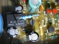
I assume it's safe to solder new 100k resistor on top of the suspect r31? do i need a low temp soldering iron so not to melt the joint of the old r31 on the pcb?
Any relatively small iron should be fine. Don’t worry about reflowing the solder joint or about lead length, as this is just a temporary experIment to confirm the original R31 has failed.
If the experiment fixes the issue, you’ll remove and replace the defective part. If the problem remains, you’ll continue troubleshooting.
If the experiment fixes the issue, you’ll remove and replace the defective part. If the problem remains, you’ll continue troubleshooting.
Thanks a million for your patient help, it now works fine. Shall I exchange the broken C31 by soldering from below or is it ok to leave it as is? I'm not 100% sure which pair of solder blobs to remove on the pcb.
Attachments
Last edited:
Sorry edit time expired for my previous entry
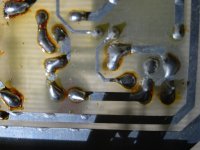
Shall I exchange the broken R31 by soldering it into the pcb from below or is it ok to leave it as is? I'm not 100% sure which pair of solder blobs to remove on the pcb. the circular shape (bottom) is C31 ?
Shall I exchange the broken R31 by soldering it into the pcb from below or is it ok to leave it as is? I'm not 100% sure which pair of solder blobs to remove on the pcb. the circular shape (bottom) is C31 ?
this is just a temporary experIment to confirm the original R31 has failed ... If the experiment fixes the issue, you’ll remove and replace the defective part.
Just to clarify for Rol G and for myself, since the amp now works may we assume that R31 was open circuit?
Of so, in order not to have to go to all the trouble of accessing the rear of the PC board to fit a new R31, could the 'temporary' resistor simply be left in place instead?
EDIT: Our posts crossed Rol G!

What about my question in post #46?
Does the time delay work and there's no switch on thump through the speakers?
Did you just leave the "temporary" R31 in place?
Do you now regard your problem as totally solved?
Does the time delay work and there's no switch on thump through the speakers?
Did you just leave the "temporary" R31 in place?
Do you now regard your problem as totally solved?
I only got as far as tacking r31 on top of the dead one.
I have not yet had time to check relais delay time, there was no thump. Still hoping for someone to pinpoint the pcb solder points. If it's safe as is, I will put the cover back on, re connect all the inputs and speakers and hope for the best.
I have not yet had time to check relais delay time, there was no thump. Still hoping for someone to pinpoint the pcb solder points. If it's safe as is, I will put the cover back on, re connect all the inputs and speakers and hope for the best.
Still hoping for someone to pinpoint the pcb solder points.
It's safe just to bridge R31 with the 100K resistor as you have done and leave it there. This removes the need to identify the solder points underneath the pcb.
You may like to shorten the bridging resistor's legs a little, but that would simply be for cosmetic reasons.
Please let us know the final outcome in order to put the thread to bed.
And, while I remember, a special thanks to @BSST for his expert input.
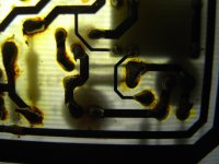
I think it's safe to leave the "graped" part as you have it. But if you want to extract the existing R31, try a bit of black electrical tape across R31's body from top side. You should be able to see its shadow when inspected from below, as in third picture of post 43.
I shall leave it as it is, re assemble the case and listen to some lovely music through this great amplifier. Thanks very much for all the great advice patience and inspiration. I learnt quite a bit.
- Home
- Amplifiers
- Solid State
- QED CD240 Amplifier Bridge Rectifier Issues