Hi,
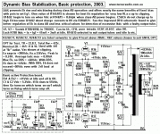
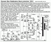
I run across interesting and simple solution of dynamic BIAS circuit designed by P.Turner. Looks like it have pros of both of fixed and cathode BIAS. However, I have some doubts that it works as intended. There are 2 versions of the schematic dated 2003 and 2014, I have attached both, and will refer in latest version in my text.
Web mirror of article, original site doesn't exists anymore.
https://www.vacuum-tube.eu/www.turneraudio.com.au/300w-5-bias-stabilizer.html
At first sight, it even protects tube against over-current and overheating, yet voltage on cathode resistors R12/R13 820 Ohm will decrease when transistors Q1/Q2 start to conduct, leaving protection circuit off. Transistors in dynamic BIAS are in series with resistors only 33 Ohm. Although hard clipping with low-frequency signal and consecutive output tube over-current is an unlikely scenario, circuit need to be more foolproof. I think R20/R21 which are in series with BJTs must be increased to 300 - 400 Ohm.
Please share your opinion and ideas. Thanks in advance.
Attachments
I've tried a few of Patrick's idea's, some work, some don't or need fettling to get them to work with your amp. I have used his protection circuit suitably modified in a few builds and that worked ok, as for his dynamic bias idea I can't comment only to recommend building a prototype and test it.
Andy.
Andy.
Yes, 33 ohm 5W makes little sense, the Bjt would getter hotter n hot without heatsink, R20/R21 should popably read 330 ohm instead.I think R20/R21 which are in series with BJTs must be increased to 300 - 400 Ohm.
Please share your opinion and ideas. Thanks in advance.
The protection circuit acts on continuous (DC) over-current level, whereas the DBS circuit acts on signal levels exceeding class A. So for normal operation with DBS the voltage on cathode resistors R12/R13 does not 'decrease', rather it doesn't 'increase'.At first sight, it even protects tube against over-current and overheating, yet voltage on cathode resistors R12/R13 820 Ohm will decrease when transistors Q1/Q2 start to conduct, leaving protection circuit off. Transistors in dynamic BIAS are in series with resistors only 33 Ohm. Although hard clipping with low-frequency signal and consecutive output tube over-current is an unlikely scenario, circuit need to be more foolproof. I think R20/R21 which are in series with BJTs must be increased to 300 - 400 Ohm.
Perhaps you should show your design workings for the operating conditions when R21/R22 'must' be increased - such as include an example worst-case duty cycle of current and time and dissipation in R21/R22, and how that relates to example output stage operation that Patrick presents. I note that Patrick presents two example circuits, as he also shows a 300W 12x 6550 output stage where R21/R22 values are modified to suit.
I suggest that unless you want to exactly copy the circuitry and amp that Patrick used for an example, then it is highly recommended that you work through the design details and fully appreciate and design for any changes you want to make. Just making changes on a whim is likely to lead to frustration and angst when something doesn't work as anticipated.