Hi,
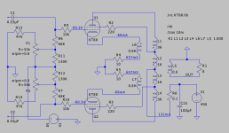
I have constructed fixed BIAS schematic which prevents power tube failure if wiper goes south. If set to necessary BIAS level, resistor network forms grid leak about 100K.
My transformer have 85V supply for BIAS.
My concern is that my design may introduce blocking distrtions becuase of too high output imedance of the BIAS supply. Please correct if I'm wrong here.
Schematic and SPICE files attached.
Thanks in advance.
Attachments
Is this a concern in practice? You are monitoring the voltage while you adjust the pot. Do they ever fail when they are set and not being monitored?
I assembled this schematic in one of my PP amps, run it with el-cheapo 6550 (not KT88), R13/R14: 47k must be reduced to 5 - 8k, because 47k forms too high grid leak resistance (over 100k).
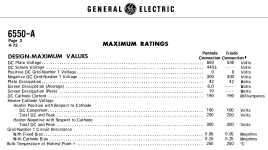
BTW, I read in RCA and GE 6550 tube data sheet that grid leak resistance with fixed bias must be 50k. Is the same true for KT88 and KT120?
BTW, I read in RCA and GE 6550 tube data sheet that grid leak resistance with fixed bias must be 50k. Is the same true for KT88 and KT120?
Attachments
Summary. I tested same set of Shuguang 6550 with same output transformer 60W 3.9K / 32% UL / 12% CFB with different amps. 100K total grid leak resistance may work and may not depending upon topology of an amp, leading to instability at very low frequencies. Lowering grid leak resistance of 6550 to recommended value (~50K) solves problem. So original schematic I posted is not good, resistor values must be lowered. Additionally, I may state, 6550 may not be direct a replacement of KT88 under certain circumstances. Max grid leak resistance of KT88/fixed bias is 100K, for 6550 - 50K.
I believe the 6550 with fixed adjustable bias has a 50k maximum g1 Rg.
I believe the 6550 with self bias has 250k maximum g1 Rg.
The often more expensive KT88:
At full dissipation has a 100K maximum g1 Rg for fixed adjustable bias;
At full dissipation has a 270k maximum g1 Rg for self bias.
These are DC resistance, they are not impedance (silly example: like the impedance of a 1uF cap to ground is not what the specification is about, grid current will eventually charge a 1uF capacitor)
Some of the modern / recently produced tubes may, or may not, meet those specifications
Buyer beware.
Prevent Thermal Run-Away. It is no fun (ask me how I know).
Your Mileage May Vary
Put another way, things like grid current variations with temperature are determined by manufacturing processes. Modern processes bear no resemblance to what TungSol and GE were doing half a century ago, so those old data sheets are meaningless. Guideposts maybe, but not reality.
All good fortune,
Chris
All good fortune,
Chris
Take a look at eurotubes.com data sheet for the JJ KT88.
It lists the maximum g1 resistance for the combination of:
Plate + Screen Watts with Fixed g1 bias (and Fixed adjustable g1 bias)
(The low dissipation range has medium Rg maximum values; the high dissipation range has very low Rg maximum values).
Plate + Screen Watts with self (cathode) bias.
(The low dissipation range has the lowest Rg maximum values; the high dissipation range has medium Rg maximum values).
As usual, the total dissipation: filament, screen, and plate, limit the maximum value of Rg.
Filament? Yes, 1.6A x 6.3V = 10.08 Watts (like a slightly too-hot type 45 plate).
And Fixed bias is a candidate for thermal run-away.
Self bias tends to self limit thermal run-away.
Follow the rules (and back off slightly from the maximum specs) and have success.
Break the rules . . . Broken Tube
- Home
- Amplifiers
- Tubes / Valves
- Q: My BIAS Schematic and Blocking Distortions