Hi,
I built 2 prototypes of push-pull KT88 amplifiers, with 3.9K 33% ultra linear / 12% cathode feedback transformer (3.9K with cathode feedback connected).
Power transformer is multiple tap so B+ can be anywhere from 400 to 500V.
Now, before assembling final variant, would like to get rid of fixed bias circuit and switch to cathode bias, with 490 - 500V B+ and 520 Ohm cathode resistor (2 x 5W metal film resistors, 300 + 220 = 520 Ohm total). Drop of max output power is not a problem.
Few questions regarding new setup.
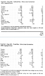
1) According to Genalex data sheet (attached), cathode bias configuration requires transformer with higher primary impedance (around 6K / 500V B+), instead of fixed bias 4.5K / 560V B+. Is that really correct?
2) What is recommended value of cathode bias resistor bypass capacitor? I saw a value of 50uF 100V. Going to use several 10uF / 22uF metal film capacitors, they are very cheap today.
3) I'm going to connect cathode feedback winding right between valve cathode and cathode bias resistor. I assume it should just work, or am I miss something?
4) In same data sheet IMD (intermodulation distortion) 50W cathode bias = 4%, yet IMD 70W fixed bias = 10%. Although output power is different (50W vs 70W), does cathode bias really have advantage of lower IMD at same output power?
Thanks in advance for any suggestion(s).
Andrei
I built 2 prototypes of push-pull KT88 amplifiers, with 3.9K 33% ultra linear / 12% cathode feedback transformer (3.9K with cathode feedback connected).
Power transformer is multiple tap so B+ can be anywhere from 400 to 500V.
Now, before assembling final variant, would like to get rid of fixed bias circuit and switch to cathode bias, with 490 - 500V B+ and 520 Ohm cathode resistor (2 x 5W metal film resistors, 300 + 220 = 520 Ohm total). Drop of max output power is not a problem.
Few questions regarding new setup.
1) According to Genalex data sheet (attached), cathode bias configuration requires transformer with higher primary impedance (around 6K / 500V B+), instead of fixed bias 4.5K / 560V B+. Is that really correct?
2) What is recommended value of cathode bias resistor bypass capacitor? I saw a value of 50uF 100V. Going to use several 10uF / 22uF metal film capacitors, they are very cheap today.
3) I'm going to connect cathode feedback winding right between valve cathode and cathode bias resistor. I assume it should just work, or am I miss something?
4) In same data sheet IMD (intermodulation distortion) 50W cathode bias = 4%, yet IMD 70W fixed bias = 10%. Although output power is different (50W vs 70W), does cathode bias really have advantage of lower IMD at same output power?
Thanks in advance for any suggestion(s).
Andrei
Attachments
Last edited:
Correct. Fixed-bias, the cathode current can rise with signal to supply a low load impedance. Cathode bias, the increased current increases bias and tends to cut the tubes off. If you beat it anyway (such as e-guitar) the bias-shift does wonky things to the sound. With huge cathode capacitors and a hi-fi mentality about clipping, it may be totally fine. You won't be in the high current zone long enough to de-bias.cathode bias configuration requires transformer with higher primary impedance
LinuksGuru,
In reference to your question:
"4) In same data sheet IMD (intermodulation distortion) 50W cathode bias = 4%, yet IMD 70W fixed bias = 10%. Although output power is different (50W vs 70W), does cathode bias really have advantage of lower IMD at same output power?"
Given a reasonably short high amplitude signal voltage of a musical transient . . .
If it does not significantly change the voltage across a very large capacitance cathode bypass capacitor (and also if that same short high amplitude signal voltage does not significantly change the capacitor voltage that goes from the driver plate to the output tube grid [no g1 grid current]):
Then 50W with fixed bias, and 50W with self bias (both amplifiers have to have the same plate to cathode voltage, the same quiescent cathode current, the same screen voltage, and the same plate to plate primary load impedance) they will have identical IMD. And, they will also have identical harmonic distortion.
Apples.
Then 70W with fixed bias, and 70W with self bias (both amplifiers have to have the same plate to cathode voltage, the same quiescent cathode current, the same screen voltage, and the same plate to plate primary load impedance) they will have identical IMD. And, they will also have identical harmonic distortion.
Pomegranates.
That is because the output tube does not "know" what kind of circuits are before it, and do not "know" what kind of circuit is after the tube, they only "know", the voltages, currents; and load impedance.
Both fixed bias, and self bias:
Note: If the RC time constants of the RC coupling are long enough, and there is a small amount of g1 grid current, there will be no voltage significantly changing across the coupling capacitor; not even for the 6Hz canon on the Telarc 1812 recording.
Self bias:
Note: If the capacitor across the self bias resistor has enough capacitance, and there is a small amount of g1 grid current, there will be no voltage significantly changing across the coupling capacitor; not even for the 6Hz canon on the Telarc 1812 recording.
In general, if you put a 20Hz sine wave into the amplifier for 1 minute, then no reasonable and practical bypass and coupling capacitors (with a small amount of g1 grid current) will be able to keep the voltage shift to a non-significant amount, the voltage will most certainly change.
Make the amplifier work on real Hi Fi and Stereo recordings of Real Music.
You are not designing a commercial amplifier to meet the "requirements" of super critical test houses.
All you want is to use the amplifier for your own musical enjoyment. Right?
Guitar amplifiers . . . they exist in another universe.
Ok, thanks for explanation. What is recommended cathode capacitor value for KT88/6550 and 240 - 270 Ohm cathode BIAS resistor? For example, 270Ohm resistor with 100uF capacitor in parallel have impedance 76.33 Ohm at 20 Hz, and 7.95 Ohm at 200 Hz.Correct. Fixed-bias, the cathode current can rise with signal to supply a low load impedance. Cathode bias, the increased current increases bias and tends to cut the tubes off. If you beat it anyway (such as e-guitar) the bias-shift does wonky things to the sound. With huge cathode capacitors and a hi-fi mentality about clipping, it may be totally fine. You won't be in the high current zone long enough to de-bias.
Out of interest why do you want to get rid of the fixed bias. I know that is does have its problems - easy to pop the KT88's, cathode bias is safer but can result in crossover distortion when overloaded due to bias shift which can take a little time to recover and is quite objectionable. It's a bit nasty if you want to show your amp to your mates. I know Mr Summer is a fan of cathode bias and I won't change his view, and that's fine. I would just say you don't want crossover distortion in a guitar amp which as they get driven in clipping so they often use fixed bias. You can break the cathode resistor into a watty zener and smaller resistor to stop the cathode voltage going up too much but at the expense of DC stability. I use servo bias - and you can buy servo bias boards for KT88's, or I can send you a design which I use. Even servo bias can get tricked with highly asymmetric waveforms.
Last edited:
I built several PP amps with fixed bias, now have an idea to simplify some things yet making all construction more error-proof. Drop of power from 60W to 50W is not a problem. As previously suggested, using big cathode capacitor may solve problem with BIAS shift and crossover distortions. 270 Ohm cathode bias resistor even with relatively small 200uF capacitor in parallel have impedance only 39 Ohm at 20 Hz. In that case its possible to use film capacitors for ultra-high reliability.Out of interest why do you want to get rid of the fixed bias.
Probably I'll run some simulations in LTSpice to check what and how.
You may find from a subjective point of view a shorter recovery time (20ms) is better, i don't know. Certainly, cathode bias is much less likely to destroy the KT88's both due to an error in construction, lack of negative supply or bias drift. Try the series resistor + zener on LTspice too if you have time. The more voltage across the zener the more the DC current depends on valve tolerances. I tend to use 6550's and they can have a thermal runaway problem if used in fixed bias requiring a 47K grid leak which makes driving them more difficult. KT88's say 220k but I would not go beyond 100k.
Last edited:
This change adds another time constant in the forward path of what's almost certainly a loop feedback amplifier. To minimize its effect on stability, you'd want that time constant as far away from the existing ones as possible, which means much larger. This minimizes distortion but increases settling time with signal. If the signal is spiky enough, like most music, a very very large time constant is best in all respects.
50uF capacitors come from an age when electrolytic caps were expensive, but today they're cheap. Try something like 1000uF 100VDC. Safely attach a DC voltmeter to a cathode, play some loud music, and see how much your bias changes, with your music at your volume. Most folk will be surprised how little it moves. If you have a scope to view with, that's even better.
All good fortune,
Chris
- Home
- Amplifiers
- Tubes / Valves
- Q: KT88 PP UL+CFB: Switching Fixed -> Cathode BIAS