Hi,
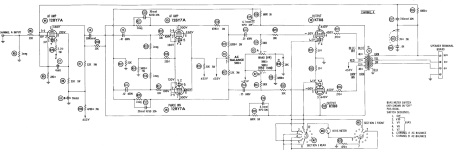
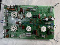
I have built Citation 2 clone on a prototyping board, and now having strange problem with HUGE Schmitt phase inverter DC balance runaway. Prior building this amp I've done extensive simulation in LTSpice (incl. THD). Schematic with voltage and a photo of my stuff attached to the bottom of this post. Need to say, I made slight changes in Schmitt phase inverter and instead of several resistors and balancing potentiometer used 5W 12K + 5.1K resistors on both 12BY7A tubes. Anode resistors resistance were intentionally increased (17.1K instead of 14.5K / 15.4K if we assume potentiometer wiper is at 50% position) in order to lower excess anode current, and to compensate my slightly higher B+ voltage 470V instead of 455 of original design. In short - top V5 tube is in a runaway state, with only 240V anode voltage instead of 300, while bottom tube anode voltage is over 400V (which means very low anode current). Changing/swapping tubes have have similar effect - huge DC balance runaway of one of the tubes, it may be bottom or top, depends upon tube selection from available stock. Finally, found a pair which balanced more or less OK, with around 300V on both anodes. However, swapping them also leads to the same large DC imbalance. I checked board several times, schematic have been assembled correctly sure for 99%. Voltage on common cathode resistor is OK, and changes only +/- few volts. When phase inverter is DC balanced, I've got slightly different un-distorted RMS voltage from both tubes. Moreover, even when badly unbalanced, it still works with a big discrepancy in output voltage. So I assume phase inverter basically works, and the problem (may be) is a thermal runaway (may be gassy tubes?). One more caveat, feeding amp with 20Hz sine-wave leads to motorboating, but I don't think its a fault of phase inverter. Unfortunately, I don't have tube tester anymore to check my current stock of several RCA/Sylvania 12BY7A tubes.
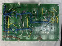
There are no overheated resistors, had installed ones with excess power rating over those listed by HK in original schematic. 3 grid stoppers of 12BY7A are with ferrite beads. GNFB can be adjusted with potentiometer, and even turned on/off with jumper wire. Heater wires lifted on around 1.5cm from bottom PCB layer (may not be clearly visible on photo).
Anyone have any idea what may went wrong?
Thanks in advance for any help.
I have built Citation 2 clone on a prototyping board, and now having strange problem with HUGE Schmitt phase inverter DC balance runaway. Prior building this amp I've done extensive simulation in LTSpice (incl. THD). Schematic with voltage and a photo of my stuff attached to the bottom of this post. Need to say, I made slight changes in Schmitt phase inverter and instead of several resistors and balancing potentiometer used 5W 12K + 5.1K resistors on both 12BY7A tubes. Anode resistors resistance were intentionally increased (17.1K instead of 14.5K / 15.4K if we assume potentiometer wiper is at 50% position) in order to lower excess anode current, and to compensate my slightly higher B+ voltage 470V instead of 455 of original design. In short - top V5 tube is in a runaway state, with only 240V anode voltage instead of 300, while bottom tube anode voltage is over 400V (which means very low anode current). Changing/swapping tubes have have similar effect - huge DC balance runaway of one of the tubes, it may be bottom or top, depends upon tube selection from available stock. Finally, found a pair which balanced more or less OK, with around 300V on both anodes. However, swapping them also leads to the same large DC imbalance. I checked board several times, schematic have been assembled correctly sure for 99%. Voltage on common cathode resistor is OK, and changes only +/- few volts. When phase inverter is DC balanced, I've got slightly different un-distorted RMS voltage from both tubes. Moreover, even when badly unbalanced, it still works with a big discrepancy in output voltage. So I assume phase inverter basically works, and the problem (may be) is a thermal runaway (may be gassy tubes?). One more caveat, feeding amp with 20Hz sine-wave leads to motorboating, but I don't think its a fault of phase inverter. Unfortunately, I don't have tube tester anymore to check my current stock of several RCA/Sylvania 12BY7A tubes.
There are no overheated resistors, had installed ones with excess power rating over those listed by HK in original schematic. 3 grid stoppers of 12BY7A are with ferrite beads. GNFB can be adjusted with potentiometer, and even turned on/off with jumper wire. Heater wires lifted on around 1.5cm from bottom PCB layer (may not be clearly visible on photo).
Anyone have any idea what may went wrong?
Thanks in advance for any help.
Attachments
Alter the design of a feedback amplifier at your peril. Very possibly it's oscillating, or at least highly unstable. That will cause all kind of strange behavior in a circuit. I would revert to the original design, follow it scrupulously and find a way to lower the B+, then see if if works properly.
I tested assembled amp, and can now confirm that everything advised by dcgillespie (Dave from AudioKarma) is 100% correct, tail resistor 270 Ohm instead of 220, separating screen split supply with 2 x 43K (away from single 22K), connecting screens of phase inverter together with 2.2uF film cap - is a working solution. No more DC balance runaway. Its not perfect because of mismatched tubes yet this is something I don't care. For anyone who wanted to eliminate this trick - you have to match phase inverter tubes by both plate and screen current. 2.2uF film cap is necessary - LTSpice simulation shows its omission raises THD. Since I eliminated 2 feedback networks from KT88/6550 plate to the input of phase inverter, GNFB need to be slightly decreased (otherwise prototype had oscillation problems at 20Hz). Input sensitivity is now 1V for max power.