Kay, only problem, in his case, g2 and the anode, both are connected to the same opt, so stabilizing only g2 is not an option
Usually I use grounded artificial center points (100R + 100R resistors) for 6.3V filament supply.
Yet this cathode follower driver 6SN7 tube is going to be connected to another 6.3V winding floating relative to GND in order to avoid excess heater-cathode voltage.
Although DC is only about -60V voltage swing needed to drive KT88 to full power is about 115V.
Hope I won't have hum problem.
PS. May be I should bias (use negative elevation) artificial center point of 2nd 6.3V winding to about -50..-60V?
I can't remember who first made the comment, but I am in the camp of thinking a tube amplifier is generally as much about the power supply design as it is about everything else. Looking at that finished and documented project of John Stewart above, a power supply based on that would solve most of the issues you are considering. Also, what is going to be on the other side of the 0.22uF coupling capacitors in the original schematic? By the time you have worked out what voltages would be needed in that stage, then won't John's solution be close to your goal?
Power supply have nothing to do with the problems solved by cathode follower driver. PP driver is universal, you can fit it into any exisitng design, e.g. Williamson, Mullard 520 or cross-coupled.
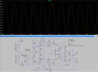
Been there; done that. (Attached). The 807 isn't a hard load by any means. I used the grid drivers to avoid the blocking problem that you have when using RC coupling. Signal peaks that turn on the grid-cathode parasitic diode will put an additional negative voltage on the grids (how RF amps derive some or all of their operating grid bias). This puts the finals into a less linear part of the plate characteristic until that excess voltage leaks off. even if you don't hear the actual clip, the excessive grid bias can degrade sonic performance. If severe enough, the finals could even cut off, what axe men call "farting out".I have a direct-coupled 6SN7 cathode follower driver idea for push-pull KT88 / 60W output. Not made any THD simulation, just basic schematic/simulation in LTSpice with voltage/current/bias numbers.
An added bonus is a few more watts. According to the STC 807 Report, the output for the 807s is 26.5W. The grid drivers allow for a bit of Class AB2 for a measured output of 32W at 1.0KHz.
Attachments
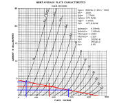
Does your loadline consider grid current, which is inevitable in class AB2? If so, how did you calculate it?
Best regards!
Best regards!
^^^^
No, it doesn't. I discovered that I was getting a few more watts than the spec mentioned during testing. The 807 isn't a difficult load, It's not going very far into AB2, so not loading the 6SN7s to any significant extent. More difficult loads and/or deeper into AB2 would require beefier cathode followers such as 6BX7s or MOSFET source followers for more current sourcing and lower ZO. The finals were designed according to an example from the STC 807 Report for Class AB1.
The extra power was a happenstance and a cherry on top.

Same applies to KT88 / 6550?The 807 isn't a difficult load, It's not going very far into AB2
Plate current for 6SN7 cathode follower is set to 7.2 mA., total voltage accross plate-cathode is ~237V, plate dissipation 1.7W - very close to max spec.
According to the Philips QE06/50 datasheet, an grid input power of 0.2 W max. is required for PP class AB2 operation. I don't know how to convert this into a impedance, i. e. loadline, though.
Best regards!
Best regards!
My view on A(B)2 drivers: The problem isn't the grid power consumption or the current, any decent follower circuit can deliver the tens of mAs needed. The problem is the sudden change in current draw when the grid goes positive, this drastic impedance change can make ugly notches in the waveform if low gm tubes are used as cathode followers (it also makes interstage transformers ring like churchbells, especially at the exact moment when the grid voltage goes from positive to negative and the grid current stops flowing).
The best device for this job is a mosfet, but I prefer using tubes as followers to get more control over the voltages during startup (probably a bigger issue in DHT amps operating at high voltages). My solution is to use driver tubes with reasonably high gm and run them at fairly high quiescent currents to increase gm and make the change in current through the tube when the grid current hits less abrupt.
The best device for this job is a mosfet, but I prefer using tubes as followers to get more control over the voltages during startup (probably a bigger issue in DHT amps operating at high voltages). My solution is to use driver tubes with reasonably high gm and run them at fairly high quiescent currents to increase gm and make the change in current through the tube when the grid current hits less abrupt.
The problem isn't the grid power consumption or the current, any decent follower circuit can deliver the tens of mAs needed. The problem is the sudden change in current draw when the grid goes positive, this drastic impedance change can make ugly notches in the waveform if low gm tubes are used as cathode followers (it also makes interstage transformers ring like churchbells, especially at the exact moment when the grid voltage goes from positive to negative and the grid current stops flowing).
Ok, great, thanks, now I see meaningful explanation why low-gm 6SN7 is not an optimal solution. So it means 6N6P (12BH7 / ECC99) instead.
6N6P should be a good choice. You could aim for even higher gm by using 6E5P or similar at the cost of more sockets, more heater current and a very real risk of oscillations.
I changed schematic with 12BH7 (somewhat similar to 6N6, but my 6N6P LTSpice model is broken).
Additionally, 15K and 30K trimmer potentiometers in previous schematic are not available in model line 3386P I use, available values are 10K, 20K and 50K.
Now 10K and 20K.
Additionally, 15K and 30K trimmer potentiometers in previous schematic are not available in model line 3386P I use, available values are 10K, 20K and 50K.
Now 10K and 20K.
Attachments
Last edited:
Its an UL, it doesn't have separate screen supply.I guess there's no need to regulate all supply voltages, but a regulated power tube screen supply is a demand then.
A slight hijack, but over the years (and even decades) I thought alot about this, and came to the conclusion that the Williamson diff driver sounds better than the cathode follower configuration when pushed, so to prove this I modified my low distortion 225+225W parallel-PP UL KT90 amp which had a cathode follower but now with a high current sourced Williamson diff driver and get much better less mudled sound on the upper mid ranges.My view on A(B)2 drivers: The problem isn't the grid power consumption or the current, any decent follower circuit can deliver the tens of mAs needed. The problem is the sudden change in current draw when the grid goes positive, this drastic impedance change can make ugly notches in the waveform if low gm tubes are used as cathode followers (it also makes interstage transformers ring like churchbells, especially at the exact moment when the grid voltage goes from positive to negative and the grid current stops flowing).
The best device for this job is a mosfet, but I prefer using tubes as followers to get more control over the voltages during startup (probably a bigger issue in DHT amps operating at high voltages). My solution is to use driver tubes with reasonably high gm and run them at fairly high quiescent currents to increase gm and make the change in current through the tube when the grid current hits less abrupt.
225W per channel or 1/2 kW bridged makes alot of noise, but I put the difference in sound quality down to the output stage Miller cap, as with parallel pairs is quite high, 270pF each side which appears the cathode follower is not good damping opposing assymetric charge induced transients, unless used with high cathode currents and low value cathode resistors. The balanced Williamson type lowish impedance class A totem pole config driver (20mA) each half is the ultimate drive dumper which a CCS is good at; despite the output impedance being somewhat higher that the C follower. Retaining the coupling cap is a disadvantage as it adds a pole to the LF response but with the feedback loop damping correctly optimized, I get no hint of blocking nor instability. Maybe, someone could advise me if simulation Spice can correctly analyze output stage Miller effect. .
OMO on this fodder, quality is uppermost but I wonder if any others arrived at similar conclusions.
Bench Baron
- Home
- Amplifiers
- Tubes / Valves
- Q: 6SN7 Cathode Follower Driver Idea for PP KT88/60W