Hey Wondering if this could be the place to help get this power supply fixed? This unit was given to me by a stereo shop, and would be perfect for supplying 13.5v regulated at 10A for amplifier repair. Unfortunatly this supply isnt working right. The output gets 11vDC but as soon as any load is applied the supply goes into protection mode.
I opened it up and found one of the two caps in the center measuring open with the DVM so I replaced both the 4700uF 25v units with spare 3300uF 35v units from spare amp parts. The 4 transistors are checking up alright, as are all the diodes. I tested about have the resistors off the board, and the other half on the board. All seem to be OK.
I'm begining to suspect the voltage regulator IC is the problem. its an LM723CN LM723 - Voltage Regulator
The transformer outputs 36vAC before the large diodes, and 24vDC after the diodes. Various parts of the transformer are measuring 0v, 11vDC, 13.5vDC... etc.


I had a similar power supply die on me while using it paralleled with a car battery to drive an amp larger than the supply alone could handle. I don't know too much about repairing these things but I was able to poke around enough to find that the bridge rectifier in my power supply had shorted out. Replacing the bridge rectifier solved all my issues. Maybe you could check that out and see if thats what is ailing yours.
Those chips do fail. Get a data sheet on it and see if it's getting the voltages it should, and if it's putting out what it should. Simple troubleshooting should locate the offending part.
Here is the datasheet:
http://www.st.com/internet/com/TECHNICAL_RESOURCES/TECHNICAL_LITERATURE/DATASHEET/CD00001008.pdf
-or-
http://www.national.com/ds/LM/LM723.pdf
Here are the voltages per pin-out.
LM723CN voltages referencing ground:
Pin 1: 0 (NC)
Pin 2: 12.16
Pin 3: 11.25
Pin 4: 7.41
Pin 5: 7.10
Pin 6: 7.10
Pin 7: 0
Pin 8: 0 (NC)
Pin 9: 9.24
Pin 10: 17.0
Pin 11: 33.04
Pin 12: 33.04
Pin 13: 11.29
Pin 14: 0.004 (NC)
I really dont know much about how to troubleshoot ICs, confused with regular inputs vs inverted inputs. I'll have to read up on this stuff a bit more tomorrow.
Last edited:
A current sensing resistor is in series with the emitter of the pass transistor. That resistor may be open or have changed value or is not properly connected. Thus, any current causes so much voltage across it that the IC goes into overload mode.
It also might be a failure in the IC but I don't think so.
It also might be a failure in the IC but I don't think so.
Did the supply have a load when you measured the voltage?
It's likely that the series pass transistor on the large heatsink is defective.
With a load, what's the DC voltage from the emitter (black probe) to the base (red probe) on the transistor mounted to the large heatsink?
It's likely that the series pass transistor on the large heatsink is defective.
With a load, what's the DC voltage from the emitter (black probe) to the base (red probe) on the transistor mounted to the large heatsink?
Im sure you are speaking of the TIP41 TO-220 transsitor mounted to the small aluminum heat sync... Otherwise you might be talking about the 2 'round' shaped transsitors on the back of the supply. From the first picture, you can see blue and yellow wires running to what is the back or left of the supply... Here is where the two round transsitors live.
I'll have to check up on these things tonight.
Thanks guys!
I'll have to check up on these things tonight.
Thanks guys!
There should be a large heatsink on the outside of the power supply. The 3055/3771s (or whatever they're using) would be mounted on it.
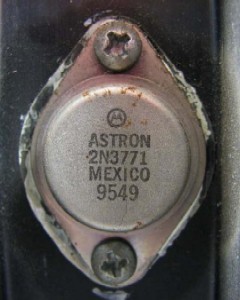
You are meaning the TO-3 transsitors which look like this:
(I'm not sure of the actual number on this particular supply; this photo is just for style-reference)
I'll test them out tonight. Thank you!
Looks like RS has these in stock. W00t!
(I'm not sure of the actual number on this particular supply; this photo is just for style-reference)
I'll test them out tonight. Thank you!
Looks like RS has these in stock. W00t!
Last edited:
- Status
- Not open for further replies.
- Home
- General Interest
- Car Audio
- Pyramid PS-15KX power supply