I have a stereo pair of Pye Mozart HF10. The amps have a damping adjustment control on the back panel. What the manual says about it is "Infinite damping is achieved with the control in the upright position. To get positive values of damping, turn the knob to the right and to get negative values of damping, turn the knob to the left, RV2 on circuit".
I've been using the amps with the control upright, because that seemed to provide most bass control, so I left them there and forgot about them. The pots are a bit dirty/worn and adjusting the control with the amp turned on makes the speakers scream scratchy sounds at what seems full output of the amp, so that also lessened my desire to play with them.
However today I did and found out I actually don't like it best upright in the "infinite damping" position - while it makes the bass response the tightest, it also seems to sound less natural than having the control in position for less than infinite damping. By less natural I mean listening to jazz for example, saxophones don't sound as right and present, also in the highs there seems to be almost like a mild "gating effect" going on, meaning very very slow volume treble detail seems to stop and start abruptly. I had never noticed it before, but it became apparent when I was listening very near field and focusing on SQ. This was somehow reflected in dynamics in general, like they become a bit abrupt not in a good way, and sometimes like there's a certain amount of "pumping" going on, like you could get using a compressor. These effects are subtle and I can't say I ever really noticed them before, but they are there.
Ok, this was using only one record (What is there to say? by Gerry Mulligan) so it's possible what I'm hearing is actually on the record and less than "infinite damping" obscures some detail by the sound being more loose, but I don't think that's it. I'm trying to understand what's going on and I'm half-guessing the damping factor adjustment affects negative feedback and what I'm hearing besides less damping is the effects of feedback.
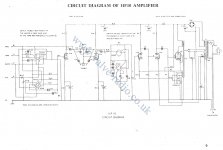
Attached is the schematic & component list, the damping adjustment control is RV2 by the output transformer. There's a question here somewhere, I'm just not sure what exactly I'm trying to ask, I guess understanding what goes on with adjusting that control would be a start, but it seems it would affect feedback of the output stage? 🙂
I've been using the amps with the control upright, because that seemed to provide most bass control, so I left them there and forgot about them. The pots are a bit dirty/worn and adjusting the control with the amp turned on makes the speakers scream scratchy sounds at what seems full output of the amp, so that also lessened my desire to play with them.
However today I did and found out I actually don't like it best upright in the "infinite damping" position - while it makes the bass response the tightest, it also seems to sound less natural than having the control in position for less than infinite damping. By less natural I mean listening to jazz for example, saxophones don't sound as right and present, also in the highs there seems to be almost like a mild "gating effect" going on, meaning very very slow volume treble detail seems to stop and start abruptly. I had never noticed it before, but it became apparent when I was listening very near field and focusing on SQ. This was somehow reflected in dynamics in general, like they become a bit abrupt not in a good way, and sometimes like there's a certain amount of "pumping" going on, like you could get using a compressor. These effects are subtle and I can't say I ever really noticed them before, but they are there.
Ok, this was using only one record (What is there to say? by Gerry Mulligan) so it's possible what I'm hearing is actually on the record and less than "infinite damping" obscures some detail by the sound being more loose, but I don't think that's it. I'm trying to understand what's going on and I'm half-guessing the damping factor adjustment affects negative feedback and what I'm hearing besides less damping is the effects of feedback.
Attached is the schematic & component list, the damping adjustment control is RV2 by the output transformer. There's a question here somewhere, I'm just not sure what exactly I'm trying to ask, I guess understanding what goes on with adjusting that control would be a start, but it seems it would affect feedback of the output stage? 🙂
Attachments

The control adjusts negative feedback, which will change things other than just output impedance.
Pye Mozart HF10 does not apply an orthodox damping factor adjustment.
In that only the amount of GNFB is adjusted whereas the true damping factor adjustment keep the GNFB about constant
and varies between voltage negative feedback and current negative feedback.
An example of this is Heathkit W6M. There is a twin potentiometer for the adjustment,
10 ohms for the current nfb and 300 ohms for voltage nfb.
I recently restored some Pye HF25 amps, which also make use of adjustable current feedback. The documentation of the Pye 25 has instructions on how to tune the current feedback setting to achieve "infinite" damping factor, and I tried it. However, I thought I could achieve (subjectively) better sound by adjusting the setting by ear.
...adjusting the control with the amp turned on makes the speakers scream scratchy sounds at what seems full output of the amp
....There's a question here somewhere, ... what goes on with adjusting that control.... 🙂
Yes, FULL output. V2a's cathode current runs through the pot. When the wiper loses contact, V2a goes "off", its plate voltage jumps a hundred Volts. V2b and the final multiply that by ~~500, or to their limits (FULL power).
That knob is there to play with. If "upright" were optimum for ALL situations, they could have stuck two fixed resistors in there; but they let you play with this aspect of the amplifier's performance. (A cynic would say that each knob added justifies a higher showroom price, especially if its function is mysterious.)
First: a 1K Linear is an inexpensive part. Replace it.
Second: running cathode current through a wiper is bad form (and bad for your ears). Without a total re-design (which I suspect won't find a perfect answer; those guys were not dumb), _I_ would consider the plan in the bottom of my attachment. A higher-value pot with fixed resistor shunts. The impedances are not quite the same, but it's basically Adjust To Taste, so there is not an exact value to hit. And there will be much less BLATTT when wiper loses contact. (And a new pot/wiper may be OK for another 50 years.)
You can also try to clean a pot. Sometimes it helps.
The drawing is a little tangled. I believe speaker current returns in R1 which is a sub-ohm resistor. So we have voltage-sense NFB through R3 R10 (very ordinary), *and* current-sense NFB from R1 into the other end of R10. With extreme connections we can make output impedance low or high. I think this plan gives a more limited range.
Do we want "Infinite Damping"? Well, no, and we can't get it. We can aim for high damping. The benefits of going over DF of 10 or 40 are dubious. And OTOH some older speakers assumed DF like 3 (no-NFB triode) or 5-10 (light NFB), and will give a different bass alignment for other damping. Also variations around every speaker impedance bend.
Also there is "ideal" or "designed" damping in an ideal room, and the bumps/lumps/dips we get in real rooms. You can sometimes "mis-tune" one to suit the "flaws" in the other.
A small trick: the far end of the secondary is not common or damp-tap but drives the cathode of V2b. Some kind of feedback; neg or pos I'm not sure, willing to trust that Pye had a reason.
The function of the 22Meg is obscure. It feeds B+ "DC" into the NFB network. I can only guess this is a buzz cancellation trick. The null will drift as C2 value changes with age or replacement. "22Meg" is suspiciously convenient (22Meg was the highest value in common resistors). It may be a clever 10-cent improvement. Since the original price is now forgotten, and the amp lives on, in a future repair I would consider upgrading the DC to a C-R-C or C-L-C filter so it didn't need this hack.
Attachments
Last edited:
Thanks for all the replies and PRR for the detailed explanation.
And yes, those pots definitely need replacing, I've tried cleaning them several times as well as I could (they are not very easy to get to without taking the amp apart) and it didn't really help much, so I turn the amp off for any adjustment.
I've changed most of the caps on the amp + got rid of the selenium rectifier. The recap was bit of a hack job, I just cut the legs off the old caps and soldered the new caps to those because this thing has a PCB (my understanding is it was one of the first) - the problem with that is to get to the component side of it, you need to desolder the transformers, so the design doesn't really favor modifications or trying out things. Full rebuild including new resistors (the old ones have drifted quite a bit) is in the plans but I haven't got around to it.
Other than damping adjustment control I was surprised at the shape of the controls. The volume pot still works in a very precise fashion and neither it nor the tone controls / selector switch suffer from any crackling. I also measured the caps after replacing them and while there was a sonic improvement, including being able to back up the treble control for 1 or 2 steps to get seemingly neutral treble response, most of them were within spec at least measured with the low voltage my tester uses. And we're talking about caps made in the late 50s, some of them electrolytics. The valves have late 50s Xf1 date codes and as far as I can tell are still fine. The amp came installed in a console thing with a Garrard 4HF record player, I doubt this thing has seen much use, my guess is it was replaced by new early transistor gear sometime in the 60s probably and sat in warm storage ever since.
I've also still to build a proper case for it, now it's all just strapped onto a blank of wood and likely will stay so until next summer, because the only place where I'm able to do any woodworking during the winter is my kitchen...
- Status
- Not open for further replies.