I have been following the site for hobby purposes for a long time. I want to make an amp for myself. I designed an amp according to the suggestions of those who do this job properly.
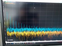
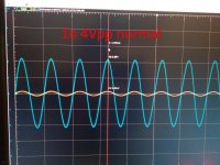
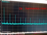
my problem is, saturation at 15V. After 6Vpp, harmonics rise.
what are your suggestions? what do i need to fix,
my problem is, saturation at 15V. After 6Vpp, harmonics rise.
what are your suggestions? what do i need to fix,
Attachments
-
puzzle.zip42.8 KB · Views: 52
-
 IMG_20200415_121614.jpg284.8 KB · Views: 56
 -
 IMG_20200415_121552.jpg279.9 KB · Views: 52
 -
 IMG_20200415_115604.jpg204.2 KB · Views: 57
 -
 IMG_20200415_115513.jpg226.8 KB · Views: 55
 -
 IMG_20200415_115501.jpg223.7 KB · Views: 118
 -
 IMG_20200415_115447.jpg225.8 KB · Views: 127
 -
 IMG_20200415_115417.jpg217 KB · Views: 127
 -
 IMG_20200415_115353.jpg205.5 KB · Views: 128
 -
 IMG_20200415_115336.jpg221.5 KB · Views: 124
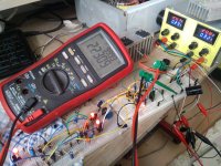
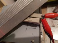
poor mans workspace.
Attachments


Last edited:
From what I'm seeing, I don't really think you have a problem.
Look at your current construction... proto-board, clip leads, push in connections, the usual snarl of jumpers... there are going to be some losses.
If you consider that you're running at plus and minus 22v, take away some losses in the output transistors, current limiting resistors etc. that probably brings you down to about 20 volts peak output. Your current testing setup probably costs you another 2 volts ... so you're at 18 or so.
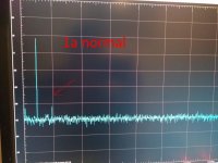
The rise in harmonics is almost certainly due to clipping and is pretty normal behaviour when you saturate an amplifier. If you are getting this behaviour at lower levels, you will want to check your input and voltage amplifier stages to be sure you aren't saturating something prematurely.
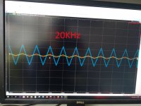
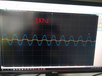
Try this ... hook up 8 ohm dummy loads ... feed it a 1khz sine wave. Increase the level until the tops and bottoms of the wave is slightly flattened, then back down a little bit... Now measure the voltage. If all is well, it's probably somewhere in the 15 to 19 volt peak range. RMS (from a voltmeter) will likely read about 12 volts.
Do the math ... P = (E x E)/R == (12 x 12)/8 == 144/8 == 18 watts RMS.
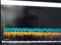
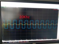
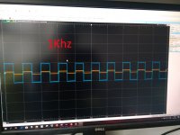
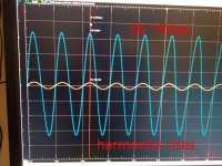
Now, watching FFT notice the behaviour when you turn the volume up just a tiny bit, those harmonics indicate clipping. If you look at the standard scope trace you will see the tops and bottoms of the sine wave are flattened ... clipped off.
Not bad for a first project.
Look at your current construction... proto-board, clip leads, push in connections, the usual snarl of jumpers... there are going to be some losses.
If you consider that you're running at plus and minus 22v, take away some losses in the output transistors, current limiting resistors etc. that probably brings you down to about 20 volts peak output. Your current testing setup probably costs you another 2 volts ... so you're at 18 or so.
The rise in harmonics is almost certainly due to clipping and is pretty normal behaviour when you saturate an amplifier. If you are getting this behaviour at lower levels, you will want to check your input and voltage amplifier stages to be sure you aren't saturating something prematurely.
Try this ... hook up 8 ohm dummy loads ... feed it a 1khz sine wave. Increase the level until the tops and bottoms of the wave is slightly flattened, then back down a little bit... Now measure the voltage. If all is well, it's probably somewhere in the 15 to 19 volt peak range. RMS (from a voltmeter) will likely read about 12 volts.
Do the math ... P = (E x E)/R == (12 x 12)/8 == 144/8 == 18 watts RMS.
Now, watching FFT notice the behaviour when you turn the volume up just a tiny bit, those harmonics indicate clipping. If you look at the standard scope trace you will see the tops and bottoms of the sine wave are flattened ... clipped off.
Not bad for a first project.
What kind/model of the usb oscilloscope are you using?
Looks nice on the screen. Can you recommend it?
Looks nice on the screen. Can you recommend it?
thanks,
input css 1.2ma
input pair 1.2ma
vas ~14ma
driver diamond css 11ma
bias 70ma
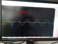
its clipped ~25vpp (+-23V power supply)
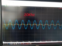
harmonics appeared at ~6Vpp
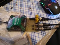
Anolog discovery 2 and self made bnc connector board 🙂
how am i discover input sections and vas saturation?
sorry for my english, i understand but not writing very well.
input css 1.2ma
input pair 1.2ma
vas ~14ma
driver diamond css 11ma
bias 70ma
its clipped ~25vpp (+-23V power supply)
harmonics appeared at ~6Vpp
Anolog discovery 2 and self made bnc connector board 🙂
how am i discover input sections and vas saturation?
sorry for my english, i understand but not writing very well.
Attachments
-
 IMG_20200415_213947.jpg305.3 KB · Views: 62
 -
 IMG_20200415_214000.jpg199 KB · Views: 60
 -
 IMG_20200415_221647.jpg281.7 KB · Views: 50
 -
 IMG_20200415_221709.jpg277.6 KB · Views: 57
 -
 IMG_20200415_221732.jpg272.5 KB · Views: 57
 -
 IMG_20200415_221748.jpg299.1 KB · Views: 52
 -
 IMG_20200415_221817.jpg301.7 KB · Views: 64
Probably gain droop in the output devices as the current increases is a factor, Early effect in various devices may also contribute - I guess the models you use don't model this?
[ Actually on further reflection as its EF output stage it could simply be crossover distortion - your circuit doesn't address this AFIACT, not sure why emulated version doesn't show this ]
[ Actually on further reflection as its EF output stage it could simply be crossover distortion - your circuit doesn't address this AFIACT, not sure why emulated version doesn't show this ]
Last edited: