My reason for working quite some time on the concept of a tweaker friendly amplifier is not much different than George's reasoning behind building his Tubelab series of prototyping rigs: flexibility!
The Tubelab
Only difference is that I am not even forty years old, let alone 40 years of tube experience") and therefore I want to share my project with you so you can spot the flaws and help improve!
and therefore I want to share my project with you so you can spot the flaws and help improve!
All the employed materials can be bough without much hassle and costs, and all machining is done by hand (sawing, drilling, hole punching).
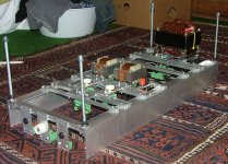
This is the amplifier I will use to describe how I proceeded. It is a plain simple, two stage SE amplifier with an ECC88 driving a 6L6. Quite simple, but ready for tweaking
The Tubelab
Only difference is that I am not even forty years old, let alone 40 years of tube experience
and therefore I want to share my project with you so you can spot the flaws and help improve!All the employed materials can be bough without much hassle and costs, and all machining is done by hand (sawing, drilling, hole punching).
This is the amplifier I will use to describe how I proceeded. It is a plain simple, two stage SE amplifier with an ECC88 driving a 6L6. Quite simple, but ready for tweaking
Attachments
The chassis
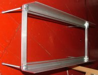
The chassis is built of aluminium profiles I could easily source from some local suppliers. I know it is not very conventional to have a narrow but deep chassis, but for this amplifier it works best, as will be made clear later on.
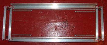
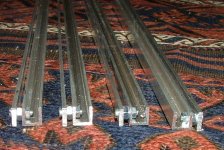
-2x L-profile 80x25, 4mm thick, 700mm long;
- 2x I profile, 8x4mm, 700mm long;
- 4x I-profile 20x5mm, 290mm long;
- several M3 and M8 bolts, nuts, rods to put everything together.
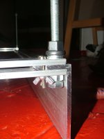
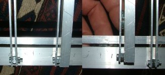
One picture shows the individual parts, cut and drilled. The second picture show one edge of the chassis. I did not have the right M8 bolt, so I took a longer one and used an additionnal nut. The idea is that the bolt goes up to half of the extended nut, so that the rod can be fixed in the remaining thread.
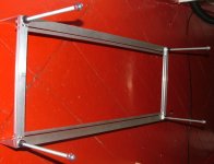
The last two are pictures of top and bottom of the chassis. The rods make it possible to easily work on the chassis when upside down, or to put the whole amplifier on its side. If the amplifier is ever finished they can be removed!
The chassis is built of aluminium profiles I could easily source from some local suppliers. I know it is not very conventional to have a narrow but deep chassis, but for this amplifier it works best, as will be made clear later on.
-2x L-profile 80x25, 4mm thick, 700mm long;
- 2x I profile, 8x4mm, 700mm long;
- 4x I-profile 20x5mm, 290mm long;
- several M3 and M8 bolts, nuts, rods to put everything together.
One picture shows the individual parts, cut and drilled. The second picture show one edge of the chassis. I did not have the right M8 bolt, so I took a longer one and used an additionnal nut. The idea is that the bolt goes up to half of the extended nut, so that the rod can be fixed in the remaining thread.
The last two are pictures of top and bottom of the chassis. The rods make it possible to easily work on the chassis when upside down, or to put the whole amplifier on its side. If the amplifier is ever finished
they can be removed!Attachments
Modular concept: The rails and modules.
I got my inspiration for this amp from the ‘control boxes’ employed in the industry. In these control boxes all components (transformers, relays, switches…) are made such that they all fit on a standardized mounting rail, allowing for easy assembling and exchanging of parts.
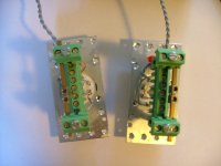
First module I present is an unfinische noval module. Furthermore pictures of finished noval and octal modules. The green terminal strips will be detailed later.
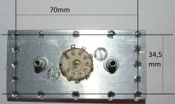
The module is cut from a 40x3mm aluminium strip, and is 80mm long. Using a perforated steel plate with a hole pattern allows for easy and precise drilling of each module.
There are four rows of holes on the edges of the module: two are 70mm apart, the other two are 34.5 mm apart. These are the values I choose as ‘standard’, that is, all modules and components (transformers, etc) should have their mounting holes or bolts on a distance of 70 and/or 34,5mm.
I got my inspiration for this amp from the ‘control boxes’ employed in the industry. In these control boxes all components (transformers, relays, switches…) are made such that they all fit on a standardized mounting rail, allowing for easy assembling and exchanging of parts.
First module I present is an unfinische noval module. Furthermore pictures of finished noval and octal modules. The green terminal strips will be detailed later.
The module is cut from a 40x3mm aluminium strip, and is 80mm long. Using a perforated steel plate with a hole pattern allows for easy and precise drilling of each module.
There are four rows of holes on the edges of the module: two are 70mm apart, the other two are 34.5 mm apart. These are the values I choose as ‘standard’, that is, all modules and components (transformers, etc) should have their mounting holes or bolts on a distance of 70 and/or 34,5mm.
Attachments
the rails
'rails/brackets' are needed to fasten the modules and components to the chassis.
The rails are made of a U profile (10x10x10 2mm thick) and a I profile (10x2mm) or 2 I profiles (10x2). These are drilled on the extremities and assembled together with a M3 bolt and nut, and a M4 nut as spacer (first picture shows 4 of these rails)
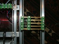
The chassis and the rails do both have an opening that is 3mm wide, as I wanted to work with M3 screws for the assembling. By coincidence I found that the M3 wingnuts come in quite handy: sliding the ‘wings’ in this opening make for a self-locking mechanism. So the rails can be loosely attached to the chassis, and the modules to the rail, one can slide them a bit until they are on the right position, and then tighten the screws and everything stays in place (second picture).
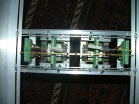
The third picture shows the back of another rail, containing two OPT’s and two loudspeaker connectors.
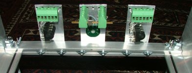
The 20x5mm I-profiles at the front and back of the amplifier have another function: holding the input/output modules, modules with volume control, etc (fourth and fifth picture).
The idea is: complete flexibility. If one decides to test a cathode follower between driver and power stage it is a matter of untightening the screws, moving them apart and drop in another set of rails with the approppriate module.
'rails/brackets' are needed to fasten the modules and components to the chassis.
The rails are made of a U profile (10x10x10 2mm thick) and a I profile (10x2mm) or 2 I profiles (10x2). These are drilled on the extremities and assembled together with a M3 bolt and nut, and a M4 nut as spacer (first picture shows 4 of these rails)
The chassis and the rails do both have an opening that is 3mm wide, as I wanted to work with M3 screws for the assembling. By coincidence I found that the M3 wingnuts come in quite handy: sliding the ‘wings’ in this opening make for a self-locking mechanism. So the rails can be loosely attached to the chassis, and the modules to the rail, one can slide them a bit until they are on the right position, and then tighten the screws and everything stays in place (second picture).
The third picture shows the back of another rail, containing two OPT’s and two loudspeaker connectors.
The 20x5mm I-profiles at the front and back of the amplifier have another function: holding the input/output modules, modules with volume control, etc (fourth and fifth picture).
The idea is: complete flexibility. If one decides to test a cathode follower between driver and power stage it is a matter of untightening the screws, moving them apart and drop in another set of rails with the approppriate module.
Attachments
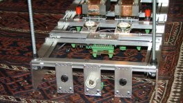
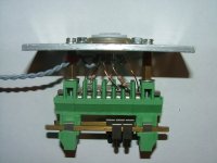
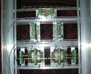
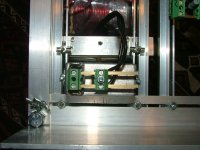
Some pictures from the inside. Transformers on the bottom of the picture, octal sockets for the 6L6 in the middle, and on top the noval socket for the ECC88.
And another picture of the socket modules.
Lets start wiring it!
And another picture of the socket modules.
Lets start wiring it!
Attachments
Last edited:
Terminal strips
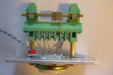
For my older projects I always used terminal strips: they never appear in a schematic, but IMHO they are essential for a tidy and safe construction of an amplifier. In a tweakers friendly amplifier the terminal strips should be very flexible, and preferably no solder!
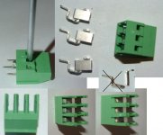
I worked with euro barrier strips, but these are bulky and tightening the screw applied a circular force on the component, tearing or destroying the wire. Some clever guys found this out and made a connector with a ‘cage’ construction: turning the screw lifts the cage and the component/wire in the receptacle is hold tight, without the circular force from the euro barrier strip.
These PCB connectors are relatively expensive when bought new, but I got 100s of them cheap from a surplus store. The picture shows how they are disassembled, the plastic body is cut, the metal part is broken in two, and eventually everything is reassembled. The lips are held in place with a drop of instant glue.
These are then glued together to form terminal strips of different lenghts / uses, such as shown before for the noval and octal modules.
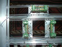
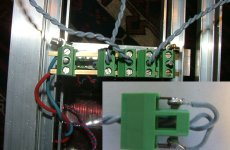
The second picture shows the noval module (again). This is a complete module of a noval socket wired for the standard double triodes (grid stopper on 2 an 7, heater on 4 and 5, copper wire on the other pins and straight to the cage). On top of the module, sustained by two PCB connectors, are two square brass rods, that can be used as a “distribution point” for B+ or as a grounding bar.
For my older projects I always used terminal strips: they never appear in a schematic, but IMHO they are essential for a tidy and safe construction of an amplifier. In a tweakers friendly amplifier the terminal strips should be very flexible, and preferably no solder!
I worked with euro barrier strips, but these are bulky and tightening the screw applied a circular force on the component, tearing or destroying the wire. Some clever guys found this out and made a connector with a ‘cage’ construction: turning the screw lifts the cage and the component/wire in the receptacle is hold tight, without the circular force from the euro barrier strip.
These PCB connectors are relatively expensive when bought new, but I got 100s of them cheap from a surplus store. The picture shows how they are disassembled, the plastic body is cut, the metal part is broken in two, and eventually everything is reassembled. The lips are held in place with a drop of instant glue.
These are then glued together to form terminal strips of different lenghts / uses, such as shown before for the noval and octal modules.
The second picture shows the noval module (again). This is a complete module of a noval socket wired for the standard double triodes (grid stopper on 2 an 7, heater on 4 and 5, copper wire on the other pins and straight to the cage). On top of the module, sustained by two PCB connectors, are two square brass rods, that can be used as a “distribution point” for B+ or as a grounding bar.
Attachments

Power supply
For the mains I use an IEC inlet whose mounting holes are spaced exaclty at 70mm. The output is fed to two brass rods, to which one can connect all power transformers. The power transformer is a big one, with several secondary voltages, as these are needed for tweaking
The second picture shows a rectifier module: four diodes and two bleeding resistors allow to use this module for bridge rectifier, bipolar supplies or voltage doubling.
The third picture shows the filaments connection to the PS. I soldered one of the PCB connectors to each of the filament supplies. In this case all valves/tubes are fed from 6,3VAC, so they can be connected in parallel as shown in the picture.
Attachments
The result of putting these components together is the amplifier shown in the first post. I have to admit this one is not ready yet, but it will surely work
In the photo gallery thread I posted pictures of a more complex amplifier, built with the same techniques. That one is PP, with input transformer, gyrator loaded drivers, fixed-bias control on output tubes, two power supplies, etc. Here is the link
In the photo gallery thread I posted pictures of a more complex amplifier, built with the same techniques. That one is PP, with input transformer, gyrator loaded drivers, fixed-bias control on output tubes, two power supplies, etc. Here is the link
Subscribed.
Are you going to add adjustable bias and feedback etc?
Fixed-bias is one of the first things I would try, I do even have the modules with potentiometers and the mosfets for source followers (I tried to make a picture, but the batteries of my camera are still charging).
The fact is that I will be moving in a couple of weeks and the audio stuff is not coming along, so I decided to take some pictures and explain a bit before everything goes into boxes for storage. In fact I have already sold my main speakers, so i can't even do serious listening anymore...
<snip>
The fact is that I will be moving in a couple of weeks and the audio stuff is not coming along, so I decided to take some pictures and explain a bit before everything goes into boxes for storage. In fact I have already sold my main speakers, so i can't even do serious listening anymore...
Ouch, sorry to hear that. Every move I have ever made the audio came with me, sometimes it was all that made the trip.. Not optional in my case. Hope the hiatus is not too long.
Hi Erik,
Very happy that you are moving to Moz. That way I was able to buy your speakers.
As one of your fans re your method. I have to admit that I admire it for its cleverness and the thought that has gone into it. And not so much for something I shall replicate (this I thought of as I was driving back that longish (for dutch standards) drive home.)
A wooden chassis is very "screwable". And transformers etc are easily added. And in fact most amplifiers have a very common basis. PSU. driver stage, output stage. etc.
This post is not a critique. But I'm trying to explain the "relative" few replies.
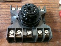
Hi. Just put this 9 pin breadboard socket together from an 11 pin "octal" relay socket, an 11 pin relay base, and the top half of a 9 pin socket saver. Had the parts in the junk bin, so it was "free". The socket savor lead plug extensions were a good fit into the 11 pin base after solder sucking out the 11 pin plug. The numbers on the terminals are correct with 10 and 11 left unused. -Fred
Attachments
- Status
- This old topic is closed. If you want to reopen this topic, contact a moderator using the "Report Post" button.
- Home
- Amplifiers
- Tubes / Valves
- Putting together a tweaker friendly amplifier!