Been collecting parts for this DAC over a couple of years. Thanks to Covid I have time to put it together. I know from near the beginning of the thread PD’s schematic for the regulator (post#4) contains an/some errors.
I have tried to follow written descriptions to make the required corrections but can’t get my regulators to work as required.
The link to a corrected schematic here is broken. Can anyone help with this again?
Is it simply that the LMZ diode needs to be rotated 180’
Or are the positions of the 470r resistor and the diode also swapped?
Thanks
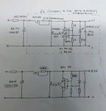
Hi Steve, here is the correct schematic:
An externally hosted image should be here but it was not working when we last tested it.
Go over every single connection one more time, make sure there's no solder bridges or bad joints, every part is right way round etc. If in doubt, check the respective datasheets for pin-outs. You will get there eventually, just be patient and methodical 🙂
Last edited:
Hi Guys, what is the voltage output vrms of a balanced 1543 when output to an amp with single ended input ?
Same as a single TDA1543 chip.
Hello, Peter. I'm currently working on the project of your DAC and will be highly appreciated, if you gonna find an oportunity to help me with next questions.
What maximum current might generate 5.5v and 8.3v power channels? So far I have 0.025A on 5.5v line and if I give more load - the voltage drops down significantly.
On 8.3v line, I managed to get max current of 0.070A and if I give more load - the voltage drops down again.
This is all just for an information, that you can use to tell me: do the power supply of your DAC (that I'm working on now) works as it should? And can you please tell me aproximate (or actual) parameters of the current, under which the power supply of the DAC, has to work?
Extremely appreciated for any help, in advance.
Attachments
Last edited:
Hi Elvis,
As the originator of the attached regulator circuits I can help you with setting the current limits to suit the load you are connecting to the output.
Let me know the load currents required from each regulator and I will re-configure the current source for you.
Regards
Paul
As the originator of the attached regulator circuits I can help you with setting the current limits to suit the load you are connecting to the output.
Let me know the load currents required from each regulator and I will re-configure the current source for you.
Regards
Paul
Hi, Paul. Thank you a lot for offering your help! That's really great and unexpected!
However, I just want to be clear: I'm not looking for opportunity for power supply to handle more load - I just want to know, if the current I'm getting now from 5.5v and 8.3v lines are matching the requirements of this particular project? Another words, is it enough for this DAC and is this how it should be or I did something wrong and now the power supply doesn't work as it's intended?
However, I just want to be clear: I'm not looking for opportunity for power supply to handle more load - I just want to know, if the current I'm getting now from 5.5v and 8.3v lines are matching the requirements of this particular project? Another words, is it enough for this DAC and is this how it should be or I did something wrong and now the power supply doesn't work as it's intended?
Hi Elvis,
In view of your information needs perhaps Peter would be the best one to help.
I will keep an eye on the thread in case you need further discussion regarding the regulator circuits.
Regards,
Paul
In view of your information needs perhaps Peter would be the best one to help.
I will keep an eye on the thread in case you need further discussion regarding the regulator circuits.
Regards,
Paul
Hi again Elvis,
The regulator drawing shows the 2.5v reference diode connected the wrong way around. The cathode should connect to the +ve rail of the regulator output. This must be an older drawing. Corrections have been posted earlier in the thread.
Regards
Paul
The regulator drawing shows the 2.5v reference diode connected the wrong way around. The cathode should connect to the +ve rail of the regulator output. This must be an older drawing. Corrections have been posted earlier in the thread.
Regards
Paul
Thank you for pointing on that, Paul. I found the correction in the late thread before starting this project and rotated the diod the way how it should be.
Just rotate the diode.
Hello, Peter. Have another question regarding your DAC. Am I understood correctly, that on CS8412 chip, the legs 24 and 7 + 24 and 8 are connected together with jamper? Or it's some mistake?
So...
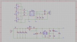
I have a simplified version of this DAC for a couple of years now and I'm really pleased with it. I always thought that some of parts for the shunt reg
are obsolete and hard to find, but i recently checked and i was wrong.
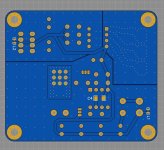
so, i scribbled up a pcb.
It would be really nice to get some feedback. did i get something wrong? can it be improved somehow?
I have a simplified version of this DAC for a couple of years now and I'm really pleased with it. I always thought that some of parts for the shunt reg
are obsolete and hard to find, but i recently checked and i was wrong.
so, i scribbled up a pcb.
It would be really nice to get some feedback. did i get something wrong? can it be improved somehow?
Attachments

Will you market this design? I am enjoying your SPDIF DAC. Will it be improvement over The SPDIF DAC?
Hi, working on upgrading my monica 2.
Are shunt regulators by Paul Hynes still available from somewhere? Thankshubert
Are shunt regulators by Paul Hynes still available from somewhere? Thankshubert
I'm placing the chips very close together to minimize traces length. There is no additional bypass on the chips, the 10uF output cap from a regulator should be placed directly on voltage and ground rails.
For I/V and Vref I'm choosing Caddock TF020 and in testing this circuit, they were preferred over nude Vishays.
Hello Peter, please advise your opinion of piggybacked TDA 1543, seems that traces will be minimized in that case. Than the value of the resistors should be recalculated or just divided ?
Thanks
How do we calculate the maximum current the shunt regulator can supply? I get that it's to do with the BSP129 resistor but haven't been able to figure out a formula, or a theoretical maximum.
I am asking because I was wondering if I could adapt it to other devices since I have the parts already and I like how it sounds.
I am asking because I was wondering if I could adapt it to other devices since I have the parts already and I like how it sounds.
Hi Uncle Leon,
I have notifications activated for new posts on this thread so I can help people who have questions regarding the PH shunt regs that have been discussed on the thread.
I am a little busy at present as nowadays I am a full time carer for a disabled family member. It is time for me to prepare food now and I will also have to attend to other care duties for the rest of the evening.
I should find time over the next few days to reply to your technical enquiry and will be pleased to help you achieve safe operation with your other proposed applications.
Regards
Paul
- Home
- More Vendors...
- Audio Sector
- Pushing the limits of TDA1543 NOS DAC