Hi guys, lately I've set my mind on building a full on vacuum tube amplifier with the case and everything and i got my hands on a pair of 6П14П's (EL84). Turns out they are quite unmatched and I've been thinking. Can i replace each cathode resistor with a transistor based constant current sink. This way i get to finely set the currents through them, thus matching them. From what i gathered, a constant current source may have a lot of perks when used correctly, like higher ripple rejection, increased linearity, spot on matching of the tubes etc. Do you think it's feasible, and how exactly can I implement such a solution?
The cost of output tubes is tiny (especially EL84s) compared to the iron, and chassis and your time. Why not get a set of tubes that are matched and don't start from a weak point?
No i meant I'm gonna encompass the finished project in a case. My question is specifically for the matching of the tubes. Whether i can match them with a CCS and will it work. For single ended i doubt it'll work, because the current source will resist variations in the current, and that's exactly what the transformer needs, but in push pull I'm not so sure if that's the case. That's why I'm asking.
If this is a guitar amp project, the thread should move to the Instruments and Amps "board".
There is a world of difference between the 6П14П (6p14p) and the 6П14П-EB (6p14p-ev), AKA EL84M. The EL84M is a very tough, genuine, 7189 equivalent that sounds pretty darned good. OTOH, the 6П14П is a quite mediocre, bordering on PoS, 6BQ5/EL84 "equivalent".
Dr. Stokes is correct. Get a properly matched set of tubes. You can "finesse" cathode current differences, but good matching of gm is essential. Buy from a reliable dealer. FWIW, my go to guy is Jim McShane.
Contrary, you need a CVS instead of a CCS.
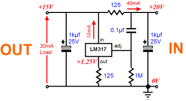
Like pictured, except the right part; connect Adj to the ground, and a trimpot instead of a 125V resistor from Out to the ground. In to cathode. Using the trimpot you can adjust needed for the particular tube current.
Like pictured, except the right part; connect Adj to the ground, and a trimpot instead of a 125V resistor from Out to the ground. In to cathode. Using the trimpot you can adjust needed for the particular tube current.
A constant voltage source? Like a zener? How would that match the tubes? I'd have to build a custom plate-grid characteristics for each tube to find out at exactly what point do the 2 currents match. That shouldn't be a problem. But won't the bias shift in time from tube deration?
Hi guys, lately I've set my mind on building a full on vacuum tube amplifier with the case and everything and i got my hands on a pair of 6П14П's (EL84). Turns out they are quite unmatched and I've been thinking. Can i replace each cathode resistor with a transistor based constant current sink. This way i get to finely set the currents through them, thus matching them. From what i gathered, a constant current source may have a lot of perks when used correctly, like higher ripple rejection, increased linearity, spot on matching of the tubes etc. Do you think it's feasible, and how exactly can I implement such a solution?
why worry that much? and how much is the mismatch?
without numbers, all we do is speculate....
and is this for guitar? if mismatched, then it may even be better...
No it's an audio amplifier. I'm not sure of the mismatch numbers. I actually do have a third tube but it's way off. The cathode voltage doesn't stop rising, so i try not to use that tube at all. I think I'll go with plain old resistors and an autobias after all. I'll just use trimmers, and I'll try to set the regimes as close as possible. The cathode resistors won't dissipate more than 1/2W so any trimmer will handle it easily. I was thinking, and both the CCS and the CVS don't seem like good ideas. The CVS doesn't provide current fixation,and frankly, it's the same as fixed bias, just at the cathode. The CCS doesn't provide the self regulation of a passive resistor. It seems the resistor gives the best of both worlds.
A constant voltage source? Like a zener? How would that match the tubes? I'd have to build a custom plate-grid characteristics for each tube to find out at exactly what point do the 2 currents match. That shouldn't be a problem. But won't the bias shift in time from tube deration?
What about all other class AB amps that have bias control pots? All the same. Add one 10 Ohm resistor in series with a trimpot and measure voltage drop on it, to set an idle current that you want.
No it's an audio amplifier. I'm not sure of the mismatch numbers. I actually do have a third tube but it's way off. The cathode voltage doesn't stop rising, so i try not to use that tube at all. I think I'll go with plain old resistors and an autobias after all. I'll just use trimmers, and I'll try to set the regimes as close as possible. The cathode resistors won't dissipate more than 1/2W so any trimmer will handle it easily. I was thinking, and both the CCS and the CVS don't seem like good ideas. The CVS doesn't provide current fixation,and frankly, it's the same as fixed bias, just at the cathode. The CCS doesn't provide the self regulation of a passive resistor. It seems the resistor gives the best of both worlds.
Yes, for class A the resistor is good. If the third tube runs away bake it in an oven on the highest possible temperature, may be a getter flash will absorb gases and heal it.
I tend to agree with this in terms of simplicity and functionality. And so does virtually the entire world of commercial manufacturers. BTW, you haven't said if this a a push-pull or single ended amplifier.It seems the resistor gives the best of both worlds.
While maintaining equal cathode current is desirable, especially for a push-pull stage to balance current flow in the output transformer, it does not necessarily mean the tubes are matched. Matched tubes refers to the tube's trans-conductance which must be measured on a curve tracer, or some other dedicated device, designed to step the signal level through several defined points at real operating levels. The best Hickoks or even that fancy Amplitrex AT-1000 won't do it. And your matching efforts are compounded by today's poor quality tubes. You'll need a good quantity of samples to get matches.
Personally I would not use adjustable resistors in the cathodes, especially if it's only single ended. You won't hear the difference between a few milliamps. But if it's push pull and you must, don't skimp on wattage. Use a good 2 watt wire wound control or even a 10 watt divider type resistor for reliability.
Oh yea, that third tube that keeps increasing current is defective. Throw it away.
Hi guys, lately I've set my mind on building a full on vacuum tube amplifier with the case and everything and i got my hands on a pair of 6П14П's (EL84). Turns out they are quite unmatched and I've been thinking. Can i replace each cathode resistor with a transistor based constant current sink. This way i get to finely set the currents through them, thus matching them. From what i gathered, a constant current source may have a lot of perks when used correctly, like higher ripple rejection, increased linearity, spot on matching of the tubes etc. Do you think it's feasible, and how exactly can I implement such a solution?
With the Push Pull circuit as you describe in the thread title you can do this at least two ways.
Are you ok to be limited to Class A operation?.
How is the driver stage coupled to the output stage?.. transformer, direct or RC coupled?
Basic idea is to have a common tail (joined cathodes) with a CCS set for the total desired current for the output pair, use a pot configured as a rheostat in the cathode circuit with a couple of current sensing resistors and you can balance the idle DC current between the tubes that way, within reason. Nice thing about IDHT is that they have cathodes, comes in handy some times - like with this.
Otherwise, seperate CCS for each tube in the cathode circuit and bridge the hot side (cathode direct) between the two tubes with a capacitor.
IME works about the best way I've heard from Class A PP stage, differential as to be correct. Class A only.
There are other ways to balance the current depending on the drive stage as per above question. I'd get 'matched' tubes as per previous suggestions but still go with the differential output with CCS tail.
I can't offer much in the way of follow up support, but google search for Allen Wright DPA 300B and downward dynamic range, and you'll get a few good hits that will point you in the right direction..
Hope this helps..
LH/S
You could use cross-coupled bias -it's like cathode bias but self-balancing:I think I'll go with plain old resistors and an autobias after all.
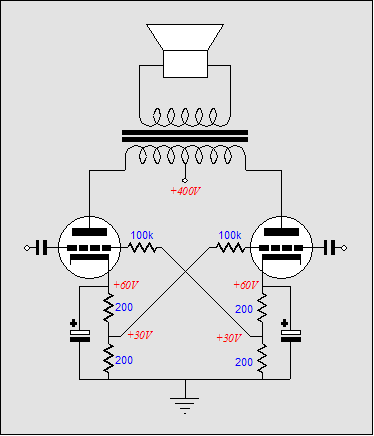
You waste voltage across the extra resistors, but in a small amp that's not such a big sacrifice.
I have a Fisher amp that had all four output tubes sharing a common cathode resistor for bias. Terrible idea. This would invariably lead to one tube red-plating when the tubes got older and were less than perfectly matched. I finally got frustrated enough to do something different.
I just made an LM317-based CCS for each tube cathode (7591) and bypassed it with a capacitor, and used that instead of a cathode resistor. It behaves like a CVS at AC but a CCS at DC. LM317 worked because 7591s don't need a lot of negative bias and don't exceed the voltage rating, but neither do EL84s.
There is no more hum out of the output stage (from the imbalance in current that the previous bias scheme was susceptible to). Balance is nearly perfect and bias sets itself automatically in the amp now. LM317s are dirt cheap. What's not to love?
Okay i read all your comments and noticed that i may have not mentioned what exactly is the circuit I'm working on. The first stage is a simple ECC83 voltage amplifier. Nothing fancy. The second part is a cathodyne phase splitter with autobias. Then an RC coupling to the power stage, which is two EL84's in pentode mode in push pull configuration. To be more specific the second grid uses 2x1kohm grid stoppers, which connect to a 2.2k/47uF filtering network and to the power supply. The HT is 320V, so the second grid voltage should be around 300V. The Ra-a is 8k. Now the only thing I have yet to decide is the cathode bias type. I read the comments and noticed two ways that it can be done with a CCS. A capacitor bypassed CCS, so that DC can be controlled tightly and AC has a low impedance path to ground. The other one is two CCS's again but AC connected through 2x large capacitors to one another. Which one should i choose? And i have another question. Not much of a question, but uncertainty. Yes I'm willing to push it a little in the class A region, so it's not pure claas B. What current should I choose at the cathode to do so.
I tend to agree with you on this. But it reminds me of something interesting I read regarding Bob Carver's VTA20S "Black Magic" power amplifier (4 EL84s) in a 2013 Absolute Sound report by Dick Olsher.I have a Fisher amp that had all four output tubes sharing a common cathode resistor for bias. Terrible idea. This would invariably lead to one tube red-plating when the tubes got older and were less than perfectly matched. I finally got frustrated enough to do something different.
"A common cathode resistor is used for all of the power output tubes. The voltage across the resistor is held constant by a Zener diode
clamp at about 14.5 volts.This helps minimize distortion during high-drive conditions. Otherwise, Carver explains,"
"As the current increases, so does the bias voltage, which makes the grids more negative, allowing distortion to go up. By using a common
cathode resistor, the bias voltage is regulated even better because, on average, with speech and music the two channels are not driven
exactly the same. This allows the least driven pair of output tubes to act as shunt regulators for the other two, helping to keep the bias
regulated. The effect is quite significant, and flies in the face of what I have always been taught - that is to use separate cathode resistors.
Not a good idea actually....I like my way the best, especially with the clamp."
I tend to agree with you on this. But it reminds me of something interesting I read regarding Bob Carver's VTA20S "Black Magic" power amplifier (4 EL84s) in a 2013 Absolute Sound report by Dick Olsher.
"A common cathode resistor is used for all of the power output tubes. The voltage across the resistor is held constant by a Zener diode
clamp at about 14.5 volts.This helps minimize distortion during high-drive conditions. Otherwise, Carver explains,"
"As the current increases, so does the bias voltage, which makes the grids more negative, allowing distortion to go up. By using a common
cathode resistor, the bias voltage is regulated even better because, on average, with speech and music the two channels are not driven
exactly the same. This allows the least driven pair of output tubes to act as shunt regulators for the other two, helping to keep the bias
regulated. The effect is quite significant, and flies in the face of what I have always been taught - that is to use separate cathode resistors.
Not a good idea actually....I like my way the best, especially with the clamp."
For sure, there are benefits to a common resistor under signal conditions. However, I just couldn't stand it anymore after the second set of tubes aged a bit and I had one red-plating again. I don't like designs that require close matching in tubes to keep from self-destruction.
The Fisher amp had a strange setup. It wasn't pure cathode bias, actually it was what I think some refer to as "combination bias", so it was cathode bias that still required adjusting. Also, the "cathode resistor" was made up of the 12AX7 filaments in parallel with a resistor. Cheap DC supply for the heaters and less heat in the chassis. It was unique, but it was a tube-eater and I got sick of feeding it.
When I do my own designs from scratch, I use fixed bias with servo and monitoring circuit that shuts the amp down if tubes ever draw too much current.
Okay so i viewed the baby huey design and i think I'll go with capacitor bypassed CCS after all. Seems simple enough, although I'd probably use a 330k resistor instead of the 5.6k for the CCS and I'll tie it to the filtered HT rail of the ECC83 power supply. In simulations doing so got me a ripple rejection of -120dB and an incredible stability. P.S. Personally i don't like resistor bias for multiple tubes. I noticed it reinforces a bit more second order distortion, because the tubes ain't symmetrically biased
Last edited:
Carver explains,"
"As the current increases, so does the bias voltage, which makes the grids more negative, allowing distortion to go up. By using a common
cathode resistor, the bias voltage is regulated even better because, on average, with speech and music the two channels are not driven
exactly the same. This allows the least driven pair of output tubes to act as shunt regulators for the other two, helping to keep the bias
regulated. The effect is quite significant, and flies in the face of what I have always been taught - that is to use separate cathode resistors.
Not a good idea actually....I like my way the best, especially with the clamp."
This seems pretty crude because it throws out any individual tube current self correction just for the sake of improvement at overdrive conditions. A far better solution is to just add George's source follower driver topology in combination with individual bypassed cathode resistors. You then get the best of both worlds. Most importantly the low impedance of the source follower will stop any tendency for the cathode biasing to ride any high volume interlude in the signal from music, etc.
A side benefit is that one can add larger cathode bypass caps if you are so inclined than would otherwise be possible. Only thing to watch for if you go for larger caps is that you will get very large current inrush at startup. You could adjust for that by making some, or most, of the negative bias come from the source follower bias part of the circuit.
- Status
- Not open for further replies.
- Home
- Amplifiers
- Tubes / Valves
- Push Pull Tube Amplifier with CCS