Let's take this one and for the moment put aside resistance, capacitance and leakage. The remaining spec:
I assume the turns ratio and input impedance (corresponding to 8 Ohm load) are given relative to primary end points (cathode to cathode) (?). So the secondary inductance can be found as Ls = Lp*8/6600 and inductance of the one section of the primary would be Lp2 = Lp/4. Am I missing something?
| Secondary Impedance | 4 and 8 Ω |
| Primary Impedance | 6,6 kΩ |
| Turns Ratio (Np:Ns) | 40,62:1(4Ω) , 28,72:1 (8Ω) |
| Primary Inductance Lp | 591 H |
I assume the turns ratio and input impedance (corresponding to 8 Ohm load) are given relative to primary end points (cathode to cathode) (?). So the secondary inductance can be found as Ls = Lp*8/6600 and inductance of the one section of the primary would be Lp2 = Lp/4. Am I missing something?
Last edited:
Yeah. You are missing: interwinding capacitance, capacitances to core, and leackage inductance. Core looses (Eddy currents, saturation) and winding resistances too.
Primary impedance is not a fixed value. It is (pri turns / sec turns)^2 x sec load impedance
Primary impedance is not a fixed value. It is (pri turns / sec turns)^2 x sec load impedance
Sure. I keep that in mindYeah. You are missing: interwinding capacitance, capacitances to core, and leackage inductance. Core looses (Eddy currents, saturation) and winding resistances too.
Actually no. I'm pretty sure that's a converted (matched) impedance. Primary inductance from the spec (and I'm not so sure here) is the inductance with open secondary. Anyway it must be somehow specified so I guess that's exactly it. If you use a real transformer as an impedance converter this inductance appears in parallel with an ideal impedance converter.Primary impedance is not a fixed value. It is (pri turns / sec turns)^2 x sec load impedance
Basically the question is how to read transformer specs
Last edited:
There is an spreadsheet created by Robert McLean that does the job, creates a model based on transformer parameters. It does a pretty good job, at least with Hammonds.
It seems to me you are a bit confused: primary or magnetizing inductance is a measure of how much reactive energy is needed to create the magnetic field in the core. Strictly speaking this energy is not lost nor tranfered to the secondary. It has its own looses: part of this energy is loosen in mooving the magnetic grains or domains inside the core. This creates heat in the core proportionatelly to pri voltage, and frequency.
The impedance ratio efectivelly is a measure of the impedance converting capability of the transformer.
Look a tranformer like a big puley atached to a smaller one by a chain. The big chain has more speed but less force than the smaller. Suppose the bigger is the driver. Thus, the motor (primary voltage) first need to create the torque to move the pulley directly associated with it. Once the pulley is being mooved, thus the movement is tranfered to the other by means of the chain (magnetic field in the core). But looses occur in both pulleys. Primary inductance can be associated to the torque needed to move the driven puley, impedance will be the mechanical work transfered from one to the other: energy is conservative.
Maybe we both are. Let me ask a question. What impedance will the output stage see in case of open secondary? It's not infinite. I assume it's j*w*L where L is the primary inductance. If Zl is your load impedance then primary impedance will be j*w*L || Zl*NIt seems to me you are a bit confused: primary or magnetizing inductance is a measure of how much reactive energy is needed to create the magnetic field in the core. Strictly speaking this energy is not lost nor tranfered to the secondary. It has its own looses: part of this energy is loosen in mooving the magnetic grains or domains inside the core. This creates heat in the core proportionatelly to pri voltage, and frequency.
If the secondary is left open you will see an impedance composed of: the reactive one mainly from the magnetization inductance bigger in magnitude more over at high frequencies, and a disipative mainly due to iron looses (again: saturation and eddy currents). As the secondary is open, currents are low and copper looses are small.
In the last equation, zi = zo x n^2.
In the last equation, zi = zo x n^2.
Many single ended output transformers:
If the secondary is not loaded (Not connected) . . .
The primary will resonate somewhere from about 500Hz to 2kHz.
That is caused by the primary inductance in parallel with the distributed primary capacitance.
A $50,000 10Hz to 4GHz Vector Network Analyzer, $10,000 Precision Calibration kit, and a bridge that worked from DC to tens of MHZ told the story; several output transformers were tested this way.
Do not forget that fact when you build a pentode / beam power output stage (high plate impedance, rp), no negative feedback, and forget to load the secondary; Or you use a speaker that has very high impedance in the 500Hz to 2kHz frequency range.
You will measure that peak in the midrange.
There are some 2-way speakers with 6dB/octave crossovers in the 500Hz to 2.5kHz frequency range.
The speaker impedance is peaked at or near the crossover frequency.
Oh, the same vector network analyzer, cal kit, and bridge made that measurement too.
Just saying
Last edited:
This must be a pp transformer, 591H inductance is very unlikely seMany single ended output transformers
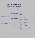
Simulaation will not come even close to the real thing, but if you include the tempo (0,04%/°C) corrected winding resistances, and 147,5H + 147,5H for the primary, and 715,29mH for the 8ohm secundary inductance, you should be able to get at least the approximate midband voltages simulated.Let's take this one and for the moment put aside resistance, capacitance and leakage. The remaining the spec:
Secondary Impedance 4 and 8 Ω Primary Impedance 6,6 kΩ Turns Ratio (Np:Ns) 40,62:1(4Ω) , 28,72:1 (8Ω) Primary Inductance Lp 591 H
I assume the turns ratio and input impedance (corresponding to 8 Ohm load) are given relative to primary end points (cathode to cathode) (?). So the secondary inductance can be found as Ls = Lp*8/6600 and inductance of the one section of the primary would be Lp2 = Lp/4. Am I missing something?
Last edited:
The elephant-in-the-room problem for making an OPT model below the midband is that primary (magnetizing) inductance and core losses (which appear as a shunt equivalent resistance) vary enormously with signal level and frequency. All this would need to be measured and entered into a table for each OPT, and issues of unbalanced DC current (some of which is dynamic with third harmonic distortion) and part-to-part variability ignored. It would be a big job, and nothing less has any reality. Big job.
All good fortune,
Chris
All good fortune,
Chris

I agree, SE into Rload perhaps, but PP? Speaker load included? Totally undoable...The elephant-in-the-room problem for making an OPT model below the midband is that primary (magnetizing) inductance and core losses (which appear as a shunt equivalent resistance) vary enormously with signal level and frequency. All this would need to be measured and entered into a table for each OPT, and issues of unbalanced DC current (some of which is dynamic with third harmonic distortion) and part-to-part variability ignored. It would be a big job, and nothing less has any reality. Big job.
All good fortune,
Chris
Oh, and i forgot the motor thingy, and and and...
This is an error. As the coupling between primary halves isn't perfect (K <1) this isn't true. L = K sqrt (L1 × L2) wence L is the total primary inductance and L1 & L2 the inductance from center tap to each plate end respectively.....147,5H + 147,5H for the primary,...
Or you can try this opt model.Try this. Of course this is too "ideal", since leakage inductance and primary capacitance is omitted.
If you need the .asc, just let me know.
Al the inductance calculation is done for you by LTspice itself.
See post #9 in
https://www.diyaudio.com/community/threads/ltspice-hierarchical-ultralinear-opt.379431/post-6847927
Do any of the “free” Spice’s that are available even have the ability to construct a proper nonlinear model that would be appropriate? I know that if you spend enough on software you can write your own code modules if you have to. The canned models have their limits.The elephant-in-the-room problem for making an OPT model below the midband is that primary (magnetizing) inductance and core losses (which appear as a shunt equivalent resistance) vary enormously with signal level and frequency. All this would need to be measured and entered into a table for each OPT, and issues of unbalanced DC current (some of which is dynamic with third harmonic distortion) and part-to-part variability ignored. It would be a big job, and nothing less has any reality. Big job.
The error is on your side, you presume k is known. It is not! You cannot include the unknown k into the simulation, would make no sense. There are to many unknown factors, even Rdc is unknown yet. The only thing known about is that k will be less than 1. He can safely take K=1 for mid frequencies. With the data given, the outcome is close enough. If you feel like being able to give the k-corrected values for L1, L2, L3 please do so. And if you are at it, may be you could even come up with a way to also include a real speaker load instead of the fictive resistive speaker load. This really would help.This is an error. As the coupling between primary halves isn't perfect (K <1) this isn't true. L = K sqrt (L1 × L2) wence L is the total primary inductance and L1 & L2 the inductance from center tap to each plate end respectively.
Last edited:
I have always the same question
How can simulate a OT when each one is different from all others?
And you haven’t on hand the real tech specification?
The Radiotron can help about theory
The only way to simulate is in the mid frequency ( less or more)
But where we need to know the limits are low end and high frequency
Simulation on OT is something like a virtual sex
Walter
- Home
- Amplifiers
- Tubes / Valves
- Push pull transformer SPICE simulation from the spec