Hey Chris, so yes, hum is present with nothing else connected. The hum slightly increases with volume once you're about 3/4 of the way up. Also, the hum changes channels with the balance control.
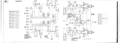
Ok guys, an update about this high voltage. It's about 10% off. I am measuring the voltage with a Radioshack DMM 22-812 which I believe has a input impedance of 10Mohm. Pin 8 on the GZ34 rectifier tube comes in at 424V. If I use my Tenma 72-6170 solid state analog multimeter, the voltage comes in at 360V. It has an imput impedance of 30Kohm. Could it be that Knight used a 1Mohm meter when they did the schematics? I don't own a 1Mohm meter to test voltages with...
I will get schematics and all voltages posted hopefully tomorrow (Sunday), and again, thanks in advance...
I will get schematics and all voltages posted hopefully tomorrow (Sunday), and again, thanks in advance...
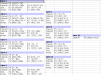
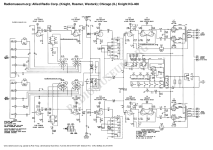
Here's are the voltages and schematics of the Knight KG-400. For the voltages, there are two measurements - the number in the parenthesis is according to the schematic - the other number is what I measured on my unit. Also, there are two schematics, and they are different - one is from the Knight assembly manual, the other is from radiomusuem.org. I had been using the one from the assembly manual - it is easier to read. Sorry for the delay, and I may have photos coming up...
Attachments
And this is when switched to a line input with shorting plugs? Or the phono input?The hum slightly increases with volume once you're about 3/4 of the way up. Also, the hum changes channels with the balance control.
Chris
Chris, I have some shorting plugs on the way - so to answer your question, no, not a line input w/ shorting plugs. However, the hum is constant across all inputs...
As already mentioned, I changed the upgraded filter caps once before, with hum still present. I just measured the ESR in them, and the came back around .24.


I can't see good enough and/or am unwilling to try to solve this with photos. At a cursory glance it looks like original canned multi-section electrolytics have been replaced with modern, hopefully Japanese, separate radial caps. Great. I'd bet on one of two possibilities causing your symptoms:
1) A replacement cap has failed (very, very unlikely) or a solder joint at the cap is flaky (always possible). Bright lights, pokey stick (unplugged and dead, dead off, and check twice). Maybe just reflow solder everywhere - no shame in shotguns.
or 2) The original and correct ground buss routing was changed somewhat during the revamp. This will be tougher to fix, because you're in for a learning curve, but it's very easily possible. Check possibilty one first, then consider the professional option of restoring quality replacement multi-section caps in original locations and wiring. Can very highly recommend Hayseed Hamfest, who make beautiful (look like spun stainless) cans with Nichicon 105C inners, to order and affordable.
Just a more general comment: fire up that scope Old Son, you won't hurt it. Start with the vertical sensitivity at 1 Volt per division, AC coupling, sweep at maybe 1 milliSecond, trigger to the channel you're using. Find a place to connect probe ground to chassis, hook probe hot somewhere not on the primary side, and take a look. All safety rules apply, of course. Big fun and free.
All good fortune,
Chris
A 10% disparity of voltage readings between a schematic & test readings is ok, that is if component specs are within limits.
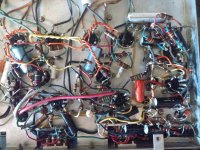
Thanks for the pics but they aren't of a good enough quality to be able to discern fine detail. From what I can see your layout is less than optimum. There's a lot of long component leads, unsupported components & what looks like less than perfect soldering. Apologies if I've offended, my remarks are intended as observations rather than criticism.
Layout, a neat layout with well dressed wiring etc not only looks good, but it means it's easier to find potential faults. Leads to valve bases should be as short as possible, this cuts down on stray C & L as well as preventing HF shenanigans.
I'm guilty of crap soldering sometimes, can't see too well so I inspect my soldering with a magnifying glass and give joints a bit of a gentle pull to make doubly sure. A dodgy joint could be the cause of hum.
Shorting plugs are easy to make at home using RCA/phono jacks or use "jump leads" to short IP to ground. By jump lead I mean a bit of wire about 8 - 10" long with croc clips on each end.
Andy.
Equal hum in both channels usually indicates that there is something wrong with something that is equally shared by both channels, but despite of that, i would interchange the 12ax7 first. Just to make sure none of those valves is faulty, by compairing theyr measured h,k,g and plate voltages to the measurements from your list (exchange only 2 at a time). V3 is, by ýour measured -10V heater to ground (instead of the -21V given in the diagram) a red flag. There should be equal voltage distribution on the heaters of valve 2, 3 and 4. Measure, not to ground, but instead the actual heater voltages, including measurement to the midpoint of each valve. Those voltages should be close to the 1/6 part of the total V2,3,4 heaterchain voltage.
Last edited:
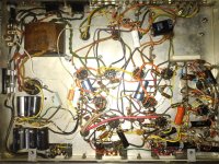
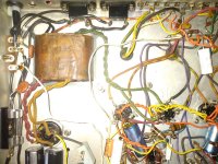
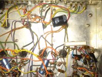
Hi Guys, thanks for the replies, and sorry for the delay. This amp was a kit - somebody wired and soldered all these components in the chassis, and this is how it turned out / how I received it. I get that it's less than ideal, and hesitated to post photos because of this. But this is how they did it in the 60's. Some of the solder joints are mine, and again, not the prettiest, but there's literally five components at one junction like the ground(s). I have never had this amp working, but have increased my skillset so one day I could get it working. Voltages are off, and I have hum in both channels. I will take a closer look at the heaters on valves 2,3,4... (thank you).
Today I lifted the AC heater line and used a DC psu to verify it wasn't the heater(s). It's not. I also reflowed some solder connections, and cleaned it up. I will say I am having a hard time getting to the ground connections. It's a bus design, and all the leads are covered in a black cloth cable tubing/insulator. I am going to have to cut it out to get to the grounds to reflow them - that is one thing I have not done. I did poke all of them with a chopstick. Thanks again - I really appreciate the input. Attached are some photos with the flash on, although I don't know how much they'll help...
Today I lifted the AC heater line and used a DC psu to verify it wasn't the heater(s). It's not. I also reflowed some solder connections, and cleaned it up. I will say I am having a hard time getting to the ground connections. It's a bus design, and all the leads are covered in a black cloth cable tubing/insulator. I am going to have to cut it out to get to the grounds to reflow them - that is one thing I have not done. I did poke all of them with a chopstick. Thanks again - I really appreciate the input. Attached are some photos with the flash on, although I don't know how much they'll help...
Attachments


Checked all ground connections - the ground bus that runs around the chassis and ends over by the AC in. It is good. I also checked shorting / grounding plugs with no luck - the hum is still present. I am going to go see which components are grounded - maybe something is grounded that shouldn't be...
Just to make sure, is the hum in both channels really equally strong present when the balancepot is midway?
Yes, the hum is noticeable mid way in both channels. When I move the balance to one side, the hum moves with it. Turning up the volume about 3/4 or more increases the hum noise. Thanks for the inquiry...
Cool. The ground buss must be connected to chassis at one and only one location. Some input jacks might fool you and connect there. If the buss is also connected somewhere else it forms a "ground loop" with symptoms like you're seeing. Worth checking anyway.
All good fortune,
Chris
All good fortune,
Chris
Yes, from what I can tell the buss semi-loops around the chassis and connects to ground near the fuse. I have experimented with removing that ground wire and connecting to for instance my dc psu to no avail. I'm not sure what it's going to take to get rid of this hum...
Yeah, but this one isn't to spec, both with its replacement B+ caps and its history of Guru-manhandling. Just trying to eliminate the most obvious possible issues first. If none of the parts or their connections are defective, and it hums, then it's not built to spec. I just never rule out human error, my own first.
All good fortune,
Chris
All good fortune,
Chris
- Home
- Amplifiers
- Tubes / Valves
- Push Pull Rectifier Trouble