I'm only an student, and I have built a few push pull amps, all using BJT output devices with a single ended driver, I just want to learn how the push pull driver works and how to design an amp using this stage. i want it to drive a push pull output stage.
Thanks for everybody !!!
Thanks for everybody !!!
I recommend you to take a look at the Leach amp
http://users.ece.gatech.edu:80/~mleach/lowtim/
There you have in many parts a classic design in the subject. Since you are new I gather that you haven't heard me nagging about my own stuff?
Check my monster phono amp and monster headphone amp. They are complex (according to some people) but still classic in many senses.
Se link below.
hugobross,
I asked this question in another thread without response...say you wanted to drive this amp with a balanced input...would you have to add a reciever stage, or is there still a way to take the feedback to the input stage?
I asked this question in another thread without response...say you wanted to drive this amp with a balanced input...would you have to add a reciever stage, or is there still a way to take the feedback to the input stage?
some info for Diogo:
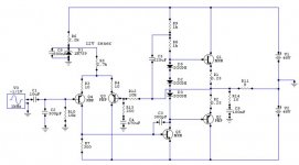
R8 and R9 are there to limit the current through the diodes, they can also be replaced by a current source
the diodes are needed to avoid crossover diistortion, also other devices are common.
Q5 is the voltage amplifier stage (C3 reduces higher frequency oscillations), the gain is equal to R12/R13
Q3 and Q4 is a differential amplifier (R3 and R4 reduces little differences between Q3 and Q4). A differential amplifier only 'allow' different signals to go through. (i.e. if the same signal is applied to the base of Q4 and to the base of Q3 there won't go a signal to the base of Q5). When no signal applied, the diff. amp. is 'in balance' => the current through Q3 (I3) is equal to the current through Q4 (I4). I ~ (12V - 0.6V)/R5 = I3 + I4
I3 = I4 so I3 = I/2. Calculation of R7: R7 = 0.6V(Ube of Q5)/I3.
HB.
I think it is very interenting, By taking the signal from the emiter the output devices are "looking" at a low impedance input, isn't it great when we talk about mosfet output devices? Won't we get a better low frequency responce?
tiroth,
I've been thinking about the same thing, I think you can do it with the same diff. amp but I'm not sure.
to diogo: sorry I see now you were looking for the push pull driver and not the single driver (sorry, I've read your question too fast)
HB.
I've been thinking about the same thing, I think you can do it with the same diff. amp but I'm not sure.
to diogo: sorry I see now you were looking for the push pull driver and not the single driver (sorry, I've read your question too fast)
HB.
No, I didn't.
But have a look a previous thread:
http://www.diyaudio.com/forums/showthread.php?threadid=5036&perpage=15&pagenumber=2
there's also a nice driver used, maybe this driver is what you're looking for.
HB.
But have a look a previous thread:
http://www.diyaudio.com/forums/showthread.php?threadid=5036&perpage=15&pagenumber=2
there's also a nice driver used, maybe this driver is what you're looking for.
HB.
- Status
- Not open for further replies.
- Home
- Amplifiers
- Solid State
- Push Pull driver newbie question