Hi, can anybody please help me i really am not understanding this... 🙁
So, i've thinking of ways to run amplifiers like TDA7294 from a simple car battery, at first i thought of stepping the 12v to around 36v and the create a reference point for the amplifier inputs there for creating a virtual ground (maybe with an op amp), but then i heard of push-pull converters, so basically what i understood was that if i use an ATX psu's transformer, you turn the 12V DC to AC by an oscillator, then feed it to the transformer's input and at the transformer's output you get a higher voltage let's say ... 28.8v if the transformer's relation is 2.4X.
First of all is this correct?
second how would i get in this case +28.8v, 0V , -28.8v from this?
I appreciate your help 😀 , thank you.
Yes, it can be done that way.
Second: by removing the windings from the atx transformer (without breaking it) and rewinding with the correct number of turns on the primary and secondary and by designing drive, rectifier, and control circuitry to match your requirements.
Look up SMPS (Switch Mode Power Supply) or DC-DC Converters.
Happy Learning.
Thank you so much for your help 😀, the thing is I still don't know much about smps , what would be the key components in making the controller to drive the transformer?
Too much to learn in one thread.
No one key component...lots of things are critical.
What is key component in car operation...lots of things are critical.
🙂
No one key component...lots of things are critical.
What is key component in car operation...lots of things are critical.
🙂
oh ok 😛
so today i got myself an atx transformer can someone please make some schamatics or tell me how to wire the transformer please??
i was thinking of making an oscilator working at 50KHZ feed the mosfets and then feed the transformer, but i don't know how to wire it 🙁
i also don't know how to create a tap to be the 0V in the +28/0/-28 configuration, there is a blob on a pin cut in half in the input and then there are 6 output pins with the exception of the thick ground wire.
can someone help me maybe?
Here's a picture of the transformer, thanks for your help 😀
Since you want to run your amp from a car battery, search threads in Car Audio - diyAudio , look for car amp schematics there , they usually show the SMPS they use.
Some designs are proprietary or very complex, some are quite basic implementantions of popular SMPS controllers.
Also google "smps controller" and read the datasheets, most have practical examples.
Be aware that practically the only useful part you'll get from a PC type SMPS will be the Ferrite core (and that will need rewinding), all other parts expect either too high (rectified line) voltages , or very low ones (typical PC 5V and 12V)
.... 1000watt carfi amps ? 😀
not much DIY...but here is a carfi power supply
12V DC Switching Power Supply - 500 Watt - Car Audio - Power Supplies
but why run home hifi on a battery ?
solar or wind power ?
heck, I want to try this for my tweeter http://classdaudio.com/amplifier-modules/mini-class-d-audio-power-amplifier.html
not much DIY...but here is a carfi power supply
12V DC Switching Power Supply - 500 Watt - Car Audio - Power Supplies
but why run home hifi on a battery ?
solar or wind power ?
heck, I want to try this for my tweeter
http://classdaudio.com/amplifier-modules/mini-class-d-audio-power-amplifier.htmlyeah i thought so...
so i can't just put 12v AC at the trasnformer and have a higher output?
i don't really know much of these transformer that work in high frequencies in comparecing with normal transformers :S
so basically i have to rewound it right?
any body know of any tool to help me calculate the number of wounds to make +30 , 0 , -30V ?
Thank you all very much 😀
Start here:
Switching-Mode Power Supply Design
then here:
PowerEsim - Free SMPS Switching Power Supply / Transformer Design Software
and so on.
Switching-Mode Power Supply Design
then here:
PowerEsim - Free SMPS Switching Power Supply / Transformer Design Software
and so on.
Yeah i have looke at those in the past but i'm only finishing my course, i dind't even talk about these power supplies, i am the one that has searched of curiousity, but thank you all 😀 , can´t i just go with a very simple switching supply, something like :
Ka7500 oscilator--> mosfets--> custom transformer (still have to figure it out)--> and the rectification and feed it to the amplifier?
Isn't it this simple? the only complication i am seeing is how to calculate the transformer's winds to step up 12v to 30v with center tap preferably with 10A at the +-30v output.
Again thank you so much for all the help, it's exactly this that helps people like me because i can see no other place i could get my questions aswered like this, it really helps me understand this "world". 😀
.... 1000watt carfi amps ? 😀
not much DIY...but here is a carfi power supply
12V DC Switching Power Supply - 500 Watt - Car Audio - Power Supplies
but why run home hifi on a battery ?
solar or wind power ?
heck, I want to try this for my tweeter
Why use battery?
it's because i want to use this on portable speakers i am building, it's my big hobbie and with this smps design i could run almost every decent amp i can buy on ebay that uses dual AC supply 😀 ( BIG PROJECTS COMING UP 😛)
can´t i just go with a very simple switching supply, something like :
Ka7500 oscilator--> mosfets--> custom transformer
Yes you can.
If you do not need a very accurate voltage control.
CD4047 + mosfets and a ETD44-ETD49 transformer... Thats it.
Primary 2x 4 turns, secondary 2x 12turns.
If some sort of control needed, look also for ex. SG3525 or TL494...
Yes you can.
If you do not need a very accurate voltage control.
CD4047 + mosfets and a ETD44-ETD49 transformer... Thats it.
Primary 2x 4 turns, secondary 2x 12turns.
If some sort of control needed, look also for ex. SG3525 or TL494...
Thank you sooo much yeah i'll probably will use something like the sg3525 to have at least some controll over the controller block of the smps,
thank you 😀
Oh yeah, could i use a toroidal core ? a large one maybe 50mm, and if i can does anybody have some kind of resource on winding toroidal transformer ? i have some small doughts on the space between winds and winding directions.
and lastly I HOPE, any AWG wire recomendations ?
...
Oh yeah, could i use a toroidal core ? a large one maybe 50mm, and if i can does anybody have some kind of resource on winding toroidal transformer ? i have some small doughts on the space between winds and winding directions.
and lastly I HOPE, any AWG wire recomendations ?
Toroids are a better shape for containing the magnetic field but are a little harder to wind. But you have to make sure the toroid is made of the correct material for your application...there are many different materials.
But you will not need that many turns so it is not too hard by hand.
As for AWG...calculate the current and remember that current rating is also dependent on temperature rise...If you allow your wires to run hotter they can carry more current...just don't get carried away.
I prefer finer stranded wire for SMPS but I have seen solid wire used.
Last advice: use fuses
🙂
hum... so how about winding with six strings of 26AWG for the primary?
what i still don´t understand is, when i'm winding the transformer do i start winding leaving no space between the windings finishing with something like this but only at the beggining :
An externally hosted image should be here but it was not working when we last tested it.
(imagine there is only one winding )
or, something spaced like this?
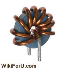
Distribute the windings evenly around the core if you can.
Or as a minimum spread them as far as possible.
Or as a minimum spread them as far as possible.
run amplifiers like TDA7294 from a simple car battery, at first i thought of stepping the 12v to around 36v ...................
First of all is this correct?
second how would i get in this case +28.8v, 0V , -28.8v
I must have missed it...........why step-up to 36V AND +-28V?
maybe i am too simple but I would use two [smaller] 12V lead-acid batteries to give 24V or +-12V
- Status
- Not open for further replies.
- Home
- Amplifiers
- Power Supplies
- Push-pull converter with atx transformer?