First of all: driver will *NOT* bias. Grid has to be allowed to float, so put a cap between VR and V1 grid.
Two. Grid needs to be able to move for amplification to occur. Put a resistor between the grid and the R1-R2 node, rather than a jumper.
Three. You'll need at least 8 volts drive for full signal. More if VR isn't at max. You'll need at least one pentode amplification stage, or two cascaded stages to run from an unamplified guitar.
Four. If you run in pentode mode, you'll get more than twice as much power, which corresponds to as much more volume. Unless you want a practice amp, this will surely be important for guitar.
Tim
Why Class A for an electric guitar amp in the first place?
Also, the grid of the input tube has a problem- it's going to want to sit at roughly 130VDC. That means you'll have to isolate it from the pot by a capacitor. I'd junk this design and start again. Use a simple diff amp in the first stage.
Also, the grid of the input tube has a problem- it's going to want to sit at roughly 130VDC. That means you'll have to isolate it from the pot by a capacitor. I'd junk this design and start again. Use a simple diff amp in the first stage.
Hi,
Either way that circuit won't fly as Tim pointed out.
Cheers,😉
Not looking for the highest quality amp--perhaps for a guitar.
Either way that circuit won't fly as Tim pointed out.
Cheers,😉
Thanks for the comments!
Let's forget the guitar amp idea for a moment. Let's say the input is from CDP which I guess has a cap output? Still need a cap between VR and V1?
Also, if the input is floated with this cap, won't the grid be slightly negative with respect to the cathode? Say, 130v compared with 132v on the cathode? Then, with an AC signal of 2 vrms...still won't work?
Won't this driver have plenty of gain for 8 volt drive to the output? Perhaps too much; like 20v or more to each output grid given a 5v pk-pk?
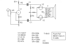
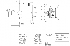
I would like to get a push pull, class A, 12ax7 with 6bq5 triode to work even if it won't sound very good. I would like to get the split load inverter design to work, too. I thought the 12ax7 would have plenty of gain even using the concertina, class A is simple, triode has less distortion and CDP has plenty of voltage.
I know this is not a good driver tube but would like to hear it...if possible.
Thanks,
Rick
Let's forget the guitar amp idea for a moment. Let's say the input is from CDP which I guess has a cap output? Still need a cap between VR and V1?
Also, if the input is floated with this cap, won't the grid be slightly negative with respect to the cathode? Say, 130v compared with 132v on the cathode? Then, with an AC signal of 2 vrms...still won't work?
Won't this driver have plenty of gain for 8 volt drive to the output? Perhaps too much; like 20v or more to each output grid given a 5v pk-pk?
I would like to get a push pull, class A, 12ax7 with 6bq5 triode to work even if it won't sound very good. I would like to get the split load inverter design to work, too. I thought the 12ax7 would have plenty of gain even using the concertina, class A is simple, triode has less distortion and CDP has plenty of voltage.
I know this is not a good driver tube but would like to hear it...if possible.
Thanks,
Rick
Hi,
Two caps in series do what? C1+C2=?
No, you don't need an extra cap...If the source is cap coupled, you don't want a second cap.
The rest of the question isn't too clear to me, so I'd leave it to someone else to answer....
Cheers, 😉
Let's forget the guitar amp idea for a moment. Let's say the input is from CDP which I guess has a cap output? Still need a cap between VR and V1?
Two caps in series do what? C1+C2=?
No, you don't need an extra cap...If the source is cap coupled, you don't want a second cap.
The rest of the question isn't too clear to me, so I'd leave it to someone else to answer....
Cheers, 😉
Indeed the cathode will be floating at a fraction of B+. Ideally, for maximum output and minimum distortion using this stage, it should be biased about 1/2B+ across the tube, which leaves 1/4B+ and 3/4B+ (measured vs. ground) for the cathode and plate resepectively.
132 is... uhm what's B+, 250V? Then unless there's a current somewhere else, there is -14V across the tube... wtf! Clearly this voltage is impossible with this type of stage.
BTW, R1 will have to be larger, more like 1k. R2 should be around 100k for a 12AX7.
If the AC signal were applied between grid and cathode, yes, it would have enough gain. But it is very difficult to apply it this way, since the signal is ground referenced. So the signal as the tube sees it is stacked on top of the voltage which appears at the tube's cathode... think about it a while and you'll see.
Fortunately, a 12AX7 (actually, a 12AU7 would have more suitable gain levels for this project) has two triodes so you can tack on an amplification stage.
Tim
132 is... uhm what's B+, 250V? Then unless there's a current somewhere else, there is -14V across the tube... wtf!
Clearly this voltage is impossible with this type of stage.BTW, R1 will have to be larger, more like 1k. R2 should be around 100k for a 12AX7.
If the AC signal were applied between grid and cathode, yes, it would have enough gain. But it is very difficult to apply it this way, since the signal is ground referenced. So the signal as the tube sees it is stacked on top of the voltage which appears at the tube's cathode... think about it a while and you'll see.
Fortunately, a 12AX7 (actually, a 12AU7 would have more suitable gain levels for this project) has two triodes so you can tack on an amplification stage.
Tim
How about this one? A nice simple design, should sound pretty decent
http://www.bonavolta.ch/hobby/en/audio/el84_5.htm
http://www.bonavolta.ch/hobby/en/audio/el84_5.htm
One 12AX7 and a pair of 6BQ5? Made me think for a while and came up with an idea using the old paraphase splitter.
Schematic
It's neither tested nor simulated, just designed it a few minutes ago. It may need tweaking. The R2-R3 junction should have around 200V. Cathode bias is individual to lessen the matching requirement. Adjust R18 for AC balance between the halves.
No feedback. Some of the distortion from V1A will propagate through V1B. Gain is highish.
Jax said:One 12AX7 and a pair of 6BQ5? Made me think for a while and came up with an idea using the old paraphase splitter.
Schematic
I like it. Similar to a 6V6 amp I built a while back.
Play with the imbalance and see if you like the sound; 5% seemed pretty nice. But ditch the 12AX7's and put in a decent sounding tube like an ECC99.
ECC99 would require some changes to my circuit though.
Change R2 and R3 to 22K 2W, R6 to 5.6K 2W, R16 and R17 to 680 ohm as a suggestion (100V Va at 5 mA).
Change R2 and R3 to 22K 2W, R6 to 5.6K 2W, R16 and R17 to 680 ohm as a suggestion (100V Va at 5 mA).
Jax said:ECC99 would require some changes to my circuit though.
I know.
Change R2 and R3 to 22K 2W, R6 to 5.6K 2W, R16 and R17 to 680 ohm as a suggestion (100V Va at 5 mA).
Waaaaaaaaaaaaaay too low an op point; they don't really wake up until 15mA. I used choke and later CCS loading in mine.
Brett said:Waaaaaaaaaaaaaay too low an op point; they don't really wake up until 15mA. I used choke and later CCS loading in mine.
I agree 😀
I just thought it was a bit hot there 🙂
No, you don't need an extra cap...If the source is cap coupled, you don't want a second cap.
Frank, you really want DC running through that pot? The required second cap is not to isolate the source but to keep the biasing DC off the pot wiper. Moot, since this is now a design for a CDP, and the "phase splitter" will now need gain.
I still maintain that a simple diff amp is still the best choice here for this application. Gain, low parts count, stability, reasonable balance, and a convenient node for any desired loop feedback.
Just breadboarding
to learn. Diff amp could be next attempt, Sy.
Tim- I do have about 100k as load to 12ax7 don't I? Makes no difference how many resistors or where they are in the series, no?
Changed R1 to 1k. Changed the input grounding, too. Lost the jumper.
Parts counts on this one is 2.5 tubes (2 6bq5 and 1/2 12ax7).
I should have 50v swing from driver, right? This would be split up to outputs?
Rick
Attachments
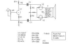
Correction: driver tube will swing from about 80 v to about 200v using 100k load resistor to be split between two output tubes. More than enough to drive the 6bq5s.
Erm... now you have a floating input. Put a 100k to 1M resistor between grid and the join between R1 and R2, put a capacitor between grid and input, and ground the ground side of input.
Tim
Tim
Thanks, Tim
Won't the 100k vol pot suffice instead of adding another grid resistor? Capacitor on the input? For CDP input, does the circuit need it? If I ground the ground side of input, won't that effectively put the grid input at -150v bias (below both the load resistor and the cathode bias resistor)?
Appreciate the comments,
Rick
No. The grid has to float on top of the cathode at its circa 75V potential.
Grounding the input will not put the grid at -150V vs. cathode because for one thing, cathode voltage will follow grid voltage naturally (and because of the nature of the circuit, plate voltage will be an inversion of this), so it wouldn't be a full 150V, and two, you use a capacitor so the grid bias is set by R1 instead.
Tim
- Status
- Not open for further replies.
- Home
- Amplifiers
- Tubes / Valves
- Push pull class A bias question