Hi.
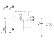
Recently I have built a power supply from 12V battery car to 200V. The output feeds a Full bridge stage and get 120Vrms after the Pass-Low filter.
The topology am using to get 200V is Push-Pull with a toroidal transformer at 50Khz.
The toroid is from ferroxcube and its material is 3c90 (OD=5.1cm, ID=3.1cm,H=1.93cm)
My goal is to get 750W at the output.
I attached the scheme
I´ve gotten 700W plus 24W dissipated in the snubber rectifiers diodes . So I think it´s cool.
At low load (saying 120W output) the efficiency is 86%. FETS don´t get warm.
I´ve wound the toroid in this sequence
-- Toroid
-- Secondary: 75 turns 2 wires AWG22
-- First Half primary: 3 turns 4 cables made each one with 60 strands AWG30
-- Second Half primary: 3 turns 4 cables made each one with 60 strands AWG30
I´m not using any kind of isolation between layers. I tried once with Craft cardboard, but I didn´t see anything different.
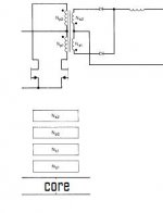
I read in Pressman´s book that the best way to wind a transformer (to reduce proximity effect) is like the pic I attached.
I wound the toroid in this way but i get 1000V peak in the diodes !!!
With my previous winding technique I´ve gotten 350V peak at the diodes
So my doubt is about if the technique that Pressman says is only about E-Cores or if am misunderstanding something about this or if there is another technique to minimize proximity effect.
Thanks in advance for your help 😉
Recently I have built a power supply from 12V battery car to 200V. The output feeds a Full bridge stage and get 120Vrms after the Pass-Low filter.
The topology am using to get 200V is Push-Pull with a toroidal transformer at 50Khz.
The toroid is from ferroxcube and its material is 3c90 (OD=5.1cm, ID=3.1cm,H=1.93cm)
My goal is to get 750W at the output.
I attached the scheme
I´ve gotten 700W plus 24W dissipated in the snubber rectifiers diodes . So I think it´s cool.
At low load (saying 120W output) the efficiency is 86%. FETS don´t get warm.
I´ve wound the toroid in this sequence
-- Toroid
-- Secondary: 75 turns 2 wires AWG22
-- First Half primary: 3 turns 4 cables made each one with 60 strands AWG30
-- Second Half primary: 3 turns 4 cables made each one with 60 strands AWG30
I´m not using any kind of isolation between layers. I tried once with Craft cardboard, but I didn´t see anything different.
I read in Pressman´s book that the best way to wind a transformer (to reduce proximity effect) is like the pic I attached.
I wound the toroid in this way but i get 1000V peak in the diodes !!!
With my previous winding technique I´ve gotten 350V peak at the diodes
So my doubt is about if the technique that Pressman says is only about E-Cores or if am misunderstanding something about this or if there is another technique to minimize proximity effect.
Thanks in advance for your help 😉
Attachments
Last edited:
Hi zaratustrax,
your schematic seems wrong: the top fets are connected in reverse side. The source shall go at gnd and the drain to the transformer.
Secondary side: why using 4 diodes and not just 2?
Transformer: the winding ratio seems strange.... With np=3+3 and ns=75+75 you will get 300v on the output if you are running unregulated at nearly 100% duty cycle.
3 turns on the primary seems low: what is your switching frequency and your Bmax in the transformer?
A push-pull transformer should minimize the leakage inductance; to do this the best way is to wind the 2 halves as a single wire in a bifilar way. Start with the 2 secondaries (bifilar) that has a smaller gauge and it is easier to wind.
Then wind the 2 primary halves (also bifilar) on top.
200v output means at least 400v on the diodes + the spikes caused by the leakage inductance, add snubbers to your diodes and also on the primary windings.
I would not use a toroidal transformer at those high voltages without a reliable insulation between pri and sec. The wire enamel is not guaranteed to withstand this.
Ciao
-marco
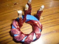
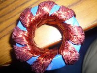
You must wind the primary first , and try to make one layer with both primaries . The secondary on top.
It's because the current in the primary is more much bigger than in sec.
Something like this. (just the primary 4+4 turns )
Attachments
Last edited:
I have stated to wind the secondary first because it use a smaller wire and it is easier to get a flat and nice winding that covers well the core.
You can try also the solution of Dimonis which is also good if you can wind the primary as good as he has done.
2) Why using a full wave rectifer on the secondary side? You can just use 2 diodes and have a center tap also on the secondary winding.
3) Another possibility for winding to improve the coupling:
- wind the primary in bifilar (as Dimonis did)
- wind the secondary on top of that
- wind another primary over the secondary (also bifilar) an parallel it with
the other primary (watch out the windings polarities!)
This will minimize the primary to primary leakage inductance (thanks to the bifilar winding) and also the primary to secondary leakage inductance (sandwich of the secondary between 2 primaries).
The sandwich has also a beneficial effects on the proximity loss in the wires.
Use many small wires in parallel both for primary and for secondary, your AWG30 will be ok.
ciao
-marco
Advantages on fullbridge on secondary AND/OR primary:Good transformer utilisation -> lots of power -> good efficiency...
Hi.
Thanks a lot everybody for your replies.
@mag:
Yes, the pic about my scheme is wrong the upper FETS polarity is wrong, but not in my board 😀
a) I am using four diodes because i just have 1 secondary, not two. As I said before, If I wind two secondaries as in the picture I showed, I get 1000V peak in the diodes
b)Ratio is ok. First and Second half primary are 3 turns, 75 turns in the secondary (Just one secondary). So, the voltage at the end will be, if 10V , (10*75)/3 =250V and if duty is 80% Vout = 250*.08 = 200
c)Frequency is 50KHz, Bmax = 1500G, Bpk= 750G is OK
@Dimonis:
Mmmm that´s a good idea, but I have a doubt because the current RMS through the primary is almost 80A that means that I need a gauge of , considering a current density of 300, 236 strands AWG30 for each half primary.
Does it matter if the two halves are one ON the another? Or should I try to lie one beside the other?
Thanks for your help.
I have stated to wind the secondary first because it use a smaller wire and it is easier to get a flat and nice winding that covers well the core.
Yes I do that! First the secondary and on it the 2 halves of the primary
OK, I will try to sandwich my toroidThe sandwich has also a beneficial effects on the proximity loss in the wires.
And should I isolated the secondary from the toroid and the primaries from secondary??
Thanks for your help
@Dimonis:
Or should I try to lie one beside the other?
Thanks for your help.
That's it , in one layer!
If you get a measurable increase in efficiency from simply changing the configuration to a full bridge rectifier then what i would do is increase the amount of copper in the secondary by an appropriate amount.
If you can figure out how much is proximity loss and how much is resistive loss then you can figure out if you should stick with the 22 awg wire you have or use something smaller.
If you can figure out how much is proximity loss and how much is resistive loss then you can figure out if you should stick with the 22 awg wire you have or use something smaller.
- Status
- Not open for further replies.
- Home
- Amplifiers
- Power Supplies
- Push-Pull 12V-200V 750w using Toroidal Transformer