Ok, so you've got a 12AX7 small signal double triode, a 6AQ5 power pentode (a 6V6-oid), an output transformer that fits this power pentode, and a complete PSU section that fits all these tubes. Why don't you just clone a Champ using all you have plus the components that differ a Champ from your device? The 6J6 can be omitted, I guess.
Best regards!
I have considered that option. The obstacle I see with doing that is the power transformer. It doesn't have the 5v secondary to feed the rectifier tube. It is also 230v-c-230v, where the champ's is 325V.
From what I understand, after the 6x5gt rectifier Id get 245DC, compared to the champs 360vdc.
Could I use a rectifier tube that could put out a higher dc voltage and use it with 6.3v?
I can assume the output transformers I have would work fine on a 6V6?
Thank you
Last edited:
This is what I make of it.
Some in certainties but it's clear,the 6J6 is just an voltage ampifier stage.
Mona
Thank you much for doing that. By voltage amplifier you mean its adding a fixed amount of gain?
So if you use solid state diodes instead of a tube rectifier, you will need a series resistor from the diode outputs to the first filter cap.
And that resistor will have to drop the same voltage as the [removed] tube rectifier did.
That will create heat, so the resistor will need to be a large wattage one.
(Carefully!) Measure the VAC from one side of the B+ secondary winding to ground.
(Carefully!) Measure the VDC at the output of the rectifier (measure across the first filter cap.
Now, a calculation is necessary to find the peak voltage to the plate of the rectifier.
VAC x 1.414 = Peak voltage to the rectifier plate.
Peak voltage to the rectifier plate - VDC across the first filter cap = the rectifier voltage drop.
Now, you need to measure the B+ current draw.
(carefully) Measure the voltage across the [400 Ohm] resistor that connects the first filter cap to the second filter cap.
The only schematic posted in this thread was another model, so you need to check the resistance there (with the unit powered down, and all caps discharged . . .Careful).
And you need to verify that B+ only goes to the 12AX7, 6J6, and 6AQ5 somewhere After that resistor.
Suppose the resistor is 400 Ohms, and the voltage drop is 12V. 12V / 400 Ohms = 30mA current.
(0.03Amps)
Suppose the voltage drop across the tube rectifier we measured and calculated above is 45V.
45V / 0.03A = 1500 Ohms
45V x 0.03A = 1.35 Watts
Use a 1500 Ohm dropping resistor, rated at 10 Watts (to keep it cool). A 5 Watt resistor could be used there, but it will run hot.
Your mileage may vary, according to the measurements you get (you have to re-calculate due to the measurements you get).
Thank you, very helpful, though it will take me some time to digest.
I meant, build a Champ (or something similar with a 6V6) around what you have, including the 6AQ5. Certainly you won't notice the small decrease in output power due to the smaller plate voltage.
Best regards!
Best regards!
Warning that the maximum ratings of the 6AQ5 are 250VDC only. I would keep tube rectifier in the amp. SS is noisier. And too high voltage can cause danger for the output transformer insulation.
I meant, build a Champ (or something similar with a 6V6) around what you have, including the 6AQ5. Certainly you won't notice the small decrease in output power due to the smaller plate voltage.
Best regards!
Similar to what Rayma suggested earlier, something like this:
Vacuum Tube Amplifiers - Tyler Gilroy
It already IS an audio amplifier.
The transformers are SMALL, for use at arm-length maybe in a crowded workroom.
It is "less than a Champ". Or any other amp you want to "imitate". I suspect closer to 2 Watts than 5.6 Watts. Which is nearly as loud (in a proper guitar speaker). That's not bad. The world is full of Champs/EpiJrs. There is interest in the old "$9.95 amps" but most of these were death-traps. This is of that clan except it is built by and for professionals.
The gain is very high for magnetic head. The gain appears to be severely bass-cut for vocal clarity (film editing is not sound balancing). It has a lot of stages but only the first one has cathode cap so the gain is not too extreme.
The 6AQ5 *MUST* have a resistor in grid 1. 100k to 500k. I dunno if the "0.002" is mis-read, or the resistor escaped, or what.
I would fix that, then neaten ALL the wiring so it looks safe to plug in. Take it out in the driveway on a long extension cord. Plug in. Wait for smoke. Wait for smoke to stop. Replace the smoked bits.
The 0.001u between little bottles is a 400Hz bass cut. There are g-amp tones this severe, makes your guitar scream, doesn't waste power where the bassist is just going to smother you. However for solo home play we usually want more bass.
"59uF"? makes no sense. Without knowing where the third leg of the Volume goes, I'd be 0.1uFd. 400V.
There's a resistor between rectifier cap and OT cap. We often retrofit such a filter on Champs for the studio. 20% less Power but 90% less buzz. I would not change this-- Movieola is used the same as a bedroom amp, close; and you should be using a better/bigger/bassier speaker than an edit squawker.
Attachments
Last edited:
...on a 6V6?
6AQ5 "is" a 6V6 "within ratings".
It is the same relative proportions built smaller. Since it appears the Moviola ran more like 220V of B+ than the 280V-380V of a "real Champ", the 6AQ5 is an excellent stand-in for 6V6.
Thank you. This is so helpful.
Without knowing where the third leg of the Volume goes, I'd be 0.1uFd. 400V.
Third leg of volume pot is grounded.
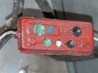
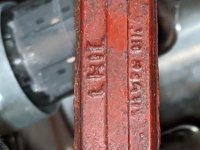
Ive attached photos of the capacitor that goes to the volume pot. I decoded with some research as 59uf. Quite possible I made a mistake.
The 6AQ5 *MUST* have a resistor in grid 1. 100k to 500k.
Ive rechecked the resistor on pin7 grid and it is indeed 470k, not 470. Would that work just as well for pin 1? If so, should I leave 0,002 in place?
Ive ordered a 6x5gt for the drive way test.
Also, Should I add a resistor or 2 to the input? There was nothing between the tape head and tube grid.
Without knowing where the third leg of the Volume goes, I'd be 0.1uFd. 400V.
Third leg of volume pot is grounded.
Ive attached photos of the capacitor that goes to the volume pot. I decoded with some research as 59uf. Quite possible I made a mistake.
The 6AQ5 *MUST* have a resistor in grid 1. 100k to 500k.
Ive rechecked the resistor on pin7 grid and it is indeed 470k, not 470. Would that work just as well for pin 1? If so, should I leave 0,002 in place?
Ive ordered a 6x5gt for the drive way test.
Also, Should I add a resistor or 2 to the input? There was nothing between the tape head and tube grid.
Attachments
Last edited:
Ive attached photos of the capacitor that goes to the volume pot. I decoded with some research as 59uf. Quite possible I made a mistake.
Sorry, capacitor value is 59pf 500v. Would that make more sense?
Sorry, capacitor value is 59pf 500v. Would that make more sense?
> 59pf 500v. Would that make more sense?
No.
I can't read doty-caps, but it looks too small to me. It *might* the the top-cut for magnetic-film playback, but not where you show it. With a 1Meg(?) volume pot, 0.01u to 0.05uFd is good coupling.
> resistor on pin7 grid and it is indeed 470k
OK. (I forgot 6AQ5 has two G1 pins.)
No.
I can't read doty-caps, but it looks too small to me. It *might* the the top-cut for magnetic-film playback, but not where you show it. With a 1Meg(?) volume pot, 0.01u to 0.05uFd is good coupling.
> resistor on pin7 grid and it is indeed 470k
OK. (I forgot 6AQ5 has two G1 pins.)
The 0.001u between little bottles is a 400Hz bass cut.
I just noticed I made another mistake in the drawing I posted. The coupling capacitor between the 6j6 plate and the grid 6aq5a is 0.001uf, not 0.1uf , and wanted to ask if its also worth changing.
Thanks
I just noticed I made another mistake in the drawing I posted. The coupling capacitor between the 6j6 plate and the grid 6aq5a is 0.001uf, not 0.1uf , and wanted to ask if its also worth changing.
Thanks
After replacing the power supply capacitors, a couple coupling capacitors, a new rectifier tube, and bypassing the 6j6, Ive plugged the circuit in and nothing blew up.
The AC voltage is 265-0-265, I measured without the Rectifier installed. After I installed the 6X5GT, the voltage out of the Cathode is 365VDC.
After the 300 ohm resistor there is 363VDC, but on the other side of the 1k resistor there does not seem to be a voltage drop. I haven't installed the other tubes yet. Is that the reason or should I look into something before installing them?
The power supply capacitors did get charged.
The Cathode resistor for the first part of the 12AX7 is 2.7K and Plate is 100K, and the rest a indicated in the drawing.
Are those safe values to start and listen once I install the tubes and connect a guitar?
I am being very cautious as it is my first tube experiment.
Thanks
Attachments
No tubes, no current, no voltage drop.
> I am being very cautious as it is my first tube experiment.
Be bold. Just load it up and plug it in.
Only do it out in the driveway so you don't stink-up the house.
And maybe first build a Lamp Limiter with a 25W and a 60W Incandescent lamp.
> I am being very cautious as it is my first tube experiment.
Be bold. Just load it up and plug it in.
Only do it out in the driveway so you don't stink-up the house.
And maybe first build a Lamp Limiter with a 25W and a 60W Incandescent lamp.
So far this diagram is what I have. I've enjoyed learning, working and playing guitar on it, and installed a larger output transformer connected to an 8 inch speaker.
With a circuit like this, is it possible to adjust certain resistance values and voltages to get cleaner sound at louder volumes? The distorted signal I get is very pleasant but I would like to see if I could get a little more volume before distortion.
I am curious if the plate voltages for the 12ax7 can or should be raised by changing the value of the 25K ohm resistor in the power supply or by the 100k and 220k plate resistors. Ive left the values of those resistors the same as they were on the old circuit which had an extra 6j6 tube.
Also curious about the value of the power supply capacitors, as Ive seen many schematics with lower values for the preamp stage.
Any suggestions I would appreciate.
Attachments
- Home
- Amplifiers
- Tubes / Valves
- purpose of 6J6 tube in amp circuit