Hi,
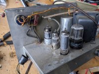
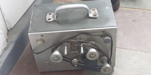
I found a box that that seems to be part of a moviola editing machine or 16mm transfer system. Inside the box is an amp consisting of a 12AX7 , then a 6J6 and a single 6AQ5A power amp.
Both sides of the 12AX7 are being used, before and after the volume pot, but only 1 side of the 6J6, which then goes in to the grid of the 6AQ5A.
The input of the amp is a monophonic tape head going straight in to the grid of the 12AX7 and the output is to a 49.7:1 transformer and 4 ohm speaker. There are no controls other than the volume/power switch.
Could anyone suggest what the purpose of the 6J6 could be?
Thanks
Attachments
If the 6J6 drives the 6AQ5, then it's just a simple gain stage for driving the EL84.
The 12AX7 is likely there to deal with the low output from the tape head, perhaps with some EQing built in.
The 12AX7 is likely there to deal with the low output from the tape head, perhaps with some EQing built in.
Thanks,
Another question I have is about the output transformer and tube compatibility.
Turns ratio of the OT is 1:49.7, for a 10k primary load with the 4ohm speaker. I measured with the 4 ohm speaker load, and a 9v ac connected to the primary.
In the data sheet for the 6aq5a, it says load resistance for Class A 5k for single end, and Effective load resistance, plate to plate, 10k for push-pull class ab for 2 tubes.
https://www.tubesandmore.com/sites/default/files/associated_files/6aq5a.pdf
Which value should I look at for a single ended circuit?
How is the 6AQ5A wired . . .
Beam Power mode?
Ultra Linear mode?
Triode Wired?
Is there Global Negative feedback?
What was the original speaker that the amp was connected to?
What was the enclosure for that speaker?
All the above create a System.
The design was probably reasonable for the use of that system.
It may, or may not, be optimum.
It almost certainly was not intended for use in a Hi Fi system.
The speaker would probably be quite near to the film editor, and not across the room (not like a home Hi Fi system).
Last edited:
This version only uses two 12AX7 stages, maybe the 6J6 was added later.
tablebeastmoviola.jpg Photo by dusty6467 | Photobucket
tablebeastmoviola.jpg Photo by dusty6467 | Photobucket
Last edited:
This is a very important thing to keep in mind.How is the 6AQ5A wired . . .
It almost certainly was not intended for use in a Hi Fi system.
it says load resistance for Class A 5k for single end,.....
That's to make the MOST out of the tube.
A Movieola is used at arms-length. It does not need the big power of a livingroom amplifier. It could use a smaller tube. However the 6BQ5 has been about as cheap, and maybe more available, than other tube types of lesser output. Higher load suits smaller output power, less heat, less current (cheaper power supply).
Likewise the 6J6 (IF original not just stuffed in to fill a hole) was a very common type. Some WWII bombers had dozens in their radar. It looked good for TV although other types (hotter or cheaper) took that field. It was always a utility tube in instrumentation and broadcast. While I have never seen it with 6J6, I have seen other dual tubes used as one half.
I am looking for a circuit to rebuild it as a guitar amplifier, so I am trying to learn a bit so to choose which circuit to imitate, and use the parts I have.
Ive measured the output transformer once again, without the 4 ohm speaker connected and turns ratio is 40:1, so 6400 ohm with 4 ohms, which seems compatible with the circuits Ive found, all very similar to the fender champ.
What would I need to change in the Champ circuit to use it with a 6aq5a? Just the plate voltage?
How Amps Work
Another Guitar Amplifier !
Usually we go from Hi Fi amp to Guitar Amplifier.
Now we go from Film Editing Amplifier to Guitar Amplifier.
Are you wanting to re-use the 6AQ5 as if it was a 6V6?
The 6V6 has higher plate voltage, screen voltage, plate dissipation, and screen dissipation; than the 6AQ5 does.
If you decide to use a 6V6 instead of the 6AQ5 . . .
You will need more room for the Octal Socket, and the bigger glass envelope of the 6V6, plus a different pin-out.
If you use the original chassis, you will have to move the 6V6 away from the other tubes, especially the rectifier and the 6J6. Think Thermal Dynamics.
Last edited:
Why? Hi Fi amps are great for air guitar.
no, i am planning on a 12ax7 and the 6AQ5.
What would I need to change in the Champ circuit to use it with a 6aq5a?
found this:
Micro Champ Amp - monster.party.hat
no, i am planning on a 12ax7 and the 6AQ5.
What would I need to change in the Champ circuit to use it with a 6aq5a?
found this:
Micro Champ Amp - monster.party.hat
Last edited:
By using an air guitar, I guess you mean an acoustic guitar with a pickup, Right?
The first thing I notice with the Micro Champ Amp you posted is that it uses solid state rectifiers.
If you use the power transformer you have, you will get more B+ volts than with the tube rectifier you have.
Perhaps that will cause the B+ to be higher than the voltage ratings of the 6AQ5 you are going to use.
Most single changes to a circuit require 3 more changes to make it work.
Last edited:
Most single changes to a circuit require 3 more changes to make it work.
For example? Id be really grateful to learn something today.
So if you use solid state diodes instead of a tube rectifier, you will need a series resistor from the diode outputs to the first filter cap.
And that resistor will have to drop the same voltage as the [removed] tube rectifier did.
That will create heat, so the resistor will need to be a large wattage one.
(Carefully!) Measure the VAC from one side of the B+ secondary winding to ground.
(Carefully!) Measure the VDC at the output of the rectifier (measure across the first filter cap.
Now, a calculation is necessary to find the peak voltage to the plate of the rectifier.
VAC x 1.414 = Peak voltage to the rectifier plate.
Peak voltage to the rectifier plate - VDC across the first filter cap = the rectifier voltage drop.
Now, you need to measure the B+ current draw.
(carefully) Measure the voltage across the [400 Ohm] resistor that connects the first filter cap to the second filter cap.
The only schematic posted in this thread was another model, so you need to check the resistance there (with the unit powered down, and all caps discharged . . .Careful).
And you need to verify that B+ only goes to the 12AX7, 6J6, and 6AQ5 somewhere After that resistor.
Suppose the resistor is 400 Ohms, and the voltage drop is 12V. 12V / 400 Ohms = 30mA current.
(0.03Amps)
Suppose the voltage drop across the tube rectifier we measured and calculated above is 45V.
45V / 0.03A = 1500 Ohms
45V x 0.03A = 1.35 Watts
Use a 1500 Ohm dropping resistor, rated at 10 Watts (to keep it cool). A 5 Watt resistor could be used there, but it will run hot.
Your mileage may vary, according to the measurements you get (you have to re-calculate due to the measurements you get).
Last edited:
Again, what did you mean by an air guitar?
And, are we talking about Jazz music, or Hard Rock music?
What kind of electronics books have you read?
You might see if your local library has a copy of the ARRL Radio Amateur's Handbook.
Try ARRL Radio Amateur Handbook - Google Search
A new version was published every year.
The best ones ran from the mid 1950s to the mid 1960s.
Lots of electronic fundamentals, and Lots of Vacuum Tube fundamentals and circuits.
Any later copy will be of help if you can not find an old copy (in fact, go online and purchase the latest one).
Last edited:
I suggest to avoid WASTING time on idle speculation based on ZERO data, you draw the circuit you already have there.
Then we have something to talk about.
You already have a functioning circuit, with power supply, proper OT, etc. which I guess is already very close to a Guitar amp.
You will need little modding, but for any suggestion we need to know what are we talking about.
So grab some paper, pencil, an eraser, put some nice background music and start drawing.
JMFahey,
And that is a good lesson to both myself, and to the original poster.
Rodrigosalvati,
Please post an [accurate] schematic of what you have.
And that is a good lesson to both myself, and to the original poster.
Rodrigosalvati,
Please post an [accurate] schematic of what you have.
Thanks, I value all the recommendations.
Attached is what I drew from the circuit that exists, to understand how it is wired.
Again, what did you mean by an air guitar?
Another Guitar Amplifier !
Usually we go from Hi Fi amp to Guitar Amplifier.
with air guitar you don't need an amp
What did you mean with "another guitar amplifier!"?
And, are we talking about Jazz music, or Hard Rock music?
are those the only options?
You already have a functioning circuit, with power supply, proper OT, etc. which I guess is already very close to a Guitar amp
Im not knowledgeable enough to make that assumption. Im trying to figure out if the OT even belonged to the circuit. The circuit is not in any condition to make a powered measurements, so I need to order parts and rebuild it, either the original, or based on a schematics.
Attachments
Ok, so you've got a 12AX7 small signal double triode, a 6AQ5 power pentode (a 6V6-oid), an output transformer that fits this power pentode, and a complete PSU section that fits all these tubes. Why don't you just clone a Champ using all you have plus the components that differ a Champ from your device? The 6J6 can be omitted, I guess.
Best regards!
Best regards!

If so, I'd parallel both 6J6 sections and halve the values of both the cathode and plate resistors.
Best regards!
Best regards!
- Home
- Amplifiers
- Tubes / Valves
- purpose of 6J6 tube in amp circuit