we have had extensive discussion about the phase splitter in the JLH amp thread. Yeah, on paper, mosfet sounds like the best phase splitter you can find. in the real world, however, BJTs seem to do a much better job, especially when you factor in the low gain and worsened linearity from a mosfet phase splitter.
We simulated quite a few mosfet phase splitters (quite incidentally used irf510 as well) and they don't perform as well as the BJTs (in terms of thd figures). However they have a huge advantage over bjt phase splitters in one department: output impedence.
Contrary to conventional wisdom, the phase splitter is NOT symmetric: its Zou is considerably higher on the collector side vs. the emitter side. This creates a problem when the phase splitter runs at low current so the mismatch is more apparent. one cure for this is to run the phase splitter at high current, thus lowering the Zout on both collector and emitter.
However, that creates a problem of its own for the BJTs: loading of the prior stage. Higher collector current means higher base current thus lower input impedance for the phase splitter. in the JLh1969 design, he runs the collector current at about 0.3ma.
Mosfet, being voltage driven (for the most part), doesn't suffer from that problem. i have found that 30-40ma is a good number to run those devices at. and that's not too far from your 20ma figure.
In real worlding listening tests, i couldn't tell mosfet phase splitters from bjt phase splitters with high levels of confidence. MOSFET seems to give more clear presentation on the high and low tho.
Another thing about those beasts: if you utilize a mosfet phase splitter in a circuitry with global feedback, make sure that it doesn't oscillate: mosfets are more prone to that than BJTs.
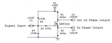
amp_man_1 said:This is the Pure Class_A Bridge Amp Driver Using Mosfet
Frequency Response 5Hz To 150KHz
Supply Voltage=+40V
Current Consumption=20mA
Max Input VACrms=4.8V
Totally Symmetric PUSH-PULL outputs
High Input Impedance~50Kohm
Low Output Impedance~1Kohm
THD<0.01%
Hi,
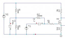
I used this cct for a while untill a friend gave me a tip for a better implementation. this difference looks small but the effect on the sound is clear
the resitor going into the i/p is not necessary if you use a VN66AFD which I think sounds good.
also if you turn the mosfet 'on' more so that the voltage accross the o/p is only about double what you think the signal will be the measured distortion decreases significantly
hope this helps
mike
Attachments
Much more better ( in all parametres ) phase inverter you get if you use only one cheap dual opams such as NE 5532 - your circuit is " prehistory "😎 .
Upupa Epops said:Much more better ( in all parametres ) phase inverter
while some calls this a phase inverter, it actually does a little bit more: it generates two output signals, 180 degrees apart.
has anyone thought about using either a differential pair or a current mirror to generate opposite signals?
Upupa Epops said:Much more better ( in all parametres ) phase inverter you get if you use only one cheap dual opams such as NE 5532 - your circuit is " prehistory "😎 .
Oh... I see
did you try both ?
which did you prefer ?
are you really sure that prehistory does not sound better ?
powered with a battery with a good cap across it I thought this cct sounded rather good
but not as good as the even more 'prehistoric' transformer volume control.
which in my universe is about as good as it gets
cheers
mike
millwood said:has anyone thought about using either a differential pair or a current mirror to generate opposite signals?
I got the same idea 😉
But I didn't launch my simulator now.
I'm not sure how to implement this design.
One possibility would be to build a 2 stage amp, with a diff pair and a PP output stage. Like an aleph (that could be used as a starting point) but with a PP output stage, driven from each leg from the diff pair
- Status
- Not open for further replies.
- Home
- Amplifiers
- Solid State
- Pure Class_A Mosfet Bridge Amp Driver