Andrew,
Sorry for that meaningless line.
My English is rather poor, so have some patience with me, please.
The base current issue can not reasonably have such a profoundness and I generally consider it as a very little problem.
I am pretty sure it is the increased gain but without trying to convince you or anyone.
Dxvideo said:http://www.diyaudio.com/forums/showthread.php?s=&threadid=104767&highlight=
I decided to make a speaker amplifier based on it.
An externally hosted image should be here but it was not working when we last tested it.
I've been inspired from Rod Eliott's "Class A Op-Amp" project to make it a pure Class A design.
Dxvideo said:
Does my input stage need
-> a single resistor load or
-> a current mirror!
I am not asking the meaning of life!!!!
Thx.
I say you start with using a single resistor.
AKSA in his AKSA 55, and I know other very experienced audio amplifier men,
say this SOUNDS The best.
As a matter of fact, the best circuit of my own,
.. a Class A basic headphone amplifier, with Capacitor output
and single supply 12 VDC,
is the best sound I have ever listened too.
My brother ordered a copy of this my own design,
as soon as he had listened to music in this amplifier.
(I have a posted topic about this Class A Single supply, resistor loaded input AND output SE amplifier.
With full details + schematics. It was in beginning of 2007, I think.)
----------
From a technical and low distortion point-of-view
current source fed input differential with mirror loading
is no doubt the best performer.
So, it is is hard to explain, why a more simple Resistor loaded input LTP pair
.. can sound better ...
I say 😉
you go try resistor first ... it is easy and good
Then if you are not satisfied 100% .. (people will never be fullt satified .. with anything 🙂 )
then you try use
current sources, servos, error corrections and mirrors all over:
there is no end what you can add to make your amplifier complicated, advanced & 'modern'.
Pure state of the art
Some amplifiers even looks as if The US. NASA Scpace Center was consulted,
to make the ultimate difficult circuit, for anybody to build
Regards, Lineup 🙂 simply and best and happy
lineup said:
AKSA in his AKSA 55, and I know other very experienced audio amplifier men,
say this SOUNDS The best.
---
From a technical and low distortion point-of-view
current source fed input differential with mirror loading
is no doubt the best performer.
So, it is is hard to explain, why a more simple Resistor loaded input LTP pair
.. can sound better ...
Regards, Lineup 🙂
... well, today, I see I have to add:
😎 current source fed circuits, can sound good, as well
but we should Always !!! try a simple resistor first, to set current
in Amplfiers
AndrewT said:from post28 is not quite accurate.
Indeed the mirror forces almost equal balancing of the load currents (close enough for most DC set-ups).
But, that does not help with balancing the collector currents, when current is sourced or sunk from the collector to load connection.
As soon as the VAS, or other connection, extracts a signal from the collector it throws the "balance" out. The current into the base of a BJT VAS can be zeroed out by adjusting the load resistance when not using a mirror, but both BJT and FET VAS will vary the collector current when charging/discharging the VAS Cob etc. and Cdom if fitted. That's why the VAS tends to perform better if it is a low capacitance type and why the Cdom if fitted can help with linearising the capacitance when VAS Vce varies.
I wonder if the mirror being incapable of this adjustment leads to the criticism often thrown at the LTP + Mirror topology for less good sound quality?
Yes it is accurate. The current mirror forces standing current balance in the LTP because the current in one leg has to match the current in the other leg, minus the base current of the VAS (which should be negligible in proportion if the amplifier is designed properly).
You simply cannot get the same degree of current balance in the LTP from a single ended resistive load unless the tail current is accurately trimmed and temperature compensated for VAS Vbe variation.
Also, I can't make sense of your reasoning WRT to the VAS capacitance. A current mirror "load" doubles the drive current for the miller capacitance and doubles the slew rate.
The linearization of the VAS by Cdom is due to the tight local negative feedback it provides and this has nothing to do with the variation in the LTP signal current.
The local negative feedback provided via Cdom around the VAS is also significantly increased (hugely when a VAS buffer is used) when the LTP is "loaded" with a current mirror, improving the VAS linearity proportionally.
As for the claims WRT to the “sound” of miller compensation and current mirror loads, the objections that are based in reality have a greater relation to poor designs with marginal slew rates and TIM problems due to insufficient LTP tail current and excessive (non-degenerated) gm and poor clipping / overload recovery which can be an issue with current mirror “loading” of the LTP if basic precautionary measures are not taken.
This is not rocket science and there is nothing mysterious about it.
Cheers,
Glen
G.Kleinschmidt said:
As for the claims WRT to the “sound” of miller compensation and current mirror loads, the objections that are based in reality have a greater relation to poor designs with marginal slew rates and TIM problems due to insufficient LTP tail current and excessive (non-degenerated) gm and poor clipping / overload recovery which can be an issue with current mirror “loading” of the LTP if basic precautionary measures are not taken.
thanks GKlein
for further explanation of this
if I try to sum it like this, am I wrong or not:
- either way we do it, the LTP balance is not 100%, when amplifier is conducting AC-signals
- there are some capacitance issues involved, and the load, the VAS,
will upset the LTP pair's accurate balance
- eventhough not solving things 100% perfect,
the current mirror, as collector load, does better than pure resistors
... if the design is well done.
In this case the sound can be very good using current mirror loading.
lineup 🙂 audio regars
lineup said:
thanks GKlein
for further explanation of this
if I try to sum it like this, am I wrong or not:
- either way we do it, the LTP balance is not 100%, when amplifier is conducting AC-signals
- there are some capacitance issues involved, and the load, the VAS,
will upset the LTP pair's accurate balance
- eventhough not solving things 100% perfect,
the current mirror, as collector load, does better than pure resistors
... if the design is well done.
In this case the sound can be very good using current mirror loading.
lineup 🙂 audio regars
I think there is some confusion here about "balance" of the LTP leg currents.
The LTP's current balance is not effected at all by the input capacitance of the VAS (including Cdom).
So long as the base current of the VAS is small in comparison to the LTP tail current and the current mirror is adequately emitter degenerated, the average current flowing in each leg of the LTP will be close enough to identical.
As for the AC signal currents in each leg of the LTP with a current mirror "load", these are nicely complementary (equal in amplitude, opposite in phase), regardless of how much current is being delivered to the VAS to drive Cdom.
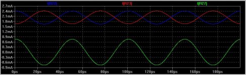
Attached below is a simulation result of a "Blameless" amp driving an oversized Cdom cap of 470pF 25Vp-p at 20kHz.
The red and blue traces are the currents in each leg of the LTP while the green trace is the drive current delivered to the VAS (predominantly to drive Cdom).
Note that because of the current mirror the AC signal current in each LTP leg only has to swing half the AC drive current required for the VAS.
Attachments
Glen,
can you obtain a plot of the LTP emitter currents that flow and superimpose them on the collector load currents of that last graph?
I think you'll find that the emitter currents are not balanced.
Can you also show the VAS base current for your model?
I suspect it alone throws the LTP balance out by more than the 1% that Self says shows an increase in distortion cf good balance.
AndrewT said:Glen,
can you obtain a plot of the LTP emitter currents that flow and superimpose them on the collector load currents of that last graph?
I think you'll find that the emitter currents are not balanced.
Can you also show the VAS base current for your model?
I suspect it alone throws the LTP balance out by more than the 1% that Self says shows an increase in distortion cf good balance.
The VAS base current is approximately 10uA - over 400 times less than the tail current. The emitter currents of the LTP transistors will only vary from the collector currents by Ib.
For all sakes and purposes, the currents are balanced.
Balancing an LTP
If LTP stage current is 2mA and beta of an 8mA VAS is 100, then Ib will be 80uA, and assuming a perfect current mirror this gives active collector at 1040uA and inactive collector at 960uA. The percentage imbalance this represents is +4%, -4%, 8% in total.
The effect can be easily countermanded with dissimilar degeneration of the current mirror.
Dissimilar degeneration of the current mirror will remedy the DC imbalance but throw out the AC balance. That is not an improvement.
Either a high beta VAS transistor an emitter follower VAS buffer should be used. With the latter, the VAS base current is made neglible. The greatest influencing factor will then most likely be the tollerance/resistance variation of the LTP the current mirror emitter degeneration resistors.
Either a high beta VAS transistor an emitter follower VAS buffer should be used. With the latter, the VAS base current is made neglible. The greatest influencing factor will then most likely be the tollerance/resistance variation of the LTP the current mirror emitter degeneration resistors.
If current through each active device of the LTP is identical, it is difficult to see how AC currents are imbalanced, particularly when, with matched devices, bias currents would be identical.
AKSA said:If current through each active device of the LTP is identical, it is difficult to see how AC currents are imbalanced, particularly when, with matched devices, bias currents would be identical.
No, it isn't difficult to see. The current mirror provides a complementary drive current to the VAS. If the current mirror has disimilar emitter degeneration then it will not act a a 1:1 current "mirror". The AC current in the leg of the LTP that drives the current mirror will then differ from that of the other leg by the modified ratio of the current mirror.
Therefore the sins of unbalanced active devices are about the same as the AC unbalance of the current mirror... and what of the fact that one device in the CM is a diode, the other is a transistor, that too will introduce unbalance.
Six to one, half a dozen to the other it seems to me.
Six to one, half a dozen to the other it seems to me.
Well, by attempting to fix the DC imbalance by unbalancing the emitter degeneration of the current mirror you are just shifting the problem somewhere else.
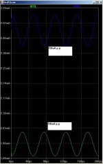
Below is a sim of what happens when the current mirror is unbalanced to compensate to the VAS bias current. In this case I deliberately made a bad VAS with a bias current of 550uA to make the degree of error visible on the graph.
The green trace is the current provided to the VAS by the current mirror leg, the blue trace is complementary current provided to the VAS from the LTP leg.
The former has a DC value 550uA less due to the 550uA sourced from the VAS. The current mirror emitter degeneration resistors are 100 ohms and 73 ohms to make the collector currents of each LTP transistor equal.
The amplitude of the green trace is equal to the amplitude of the blue trace * (73/100).
The circuit is therefore incapable of providing an accurate complementary push-pull drive current to the VAS, a common-mode AC difference signal then circulates and the THD rises somewhat proportionally.
Attachments
Thank you for the curves; I see your point, the math is clear.
I wonder if you would hear this in practice.........
I wonder if you would hear this in practice.........
Re: Balancing an LTP
I accept that the effect of the base current and of the capacitive loading should be minimised/optimised to get best performance from the LTP.
I cannot accept that a Mirror load automatically balances the LTP for best performance.
I see two factions, those that claim mirror loading of the LTP sounds best and they probably also use Cdom around the VAS, the other group who minimise Cdom or even eliminate it AND use resistor loading of the input LTP to obtain best sound.
Somehow I can never see these two groups of designers agreeing with each other. Glen appears to be in the Mirror+Cdom group but at least Glen recognises where the shortfall of this technique is and addresses it in his way.
I prefer an accurately set up LTP (balanced) with resistor loading and if possible eliminate Cdom. But my skills are lacking and I often have to add some Cdom (with a very low capacitance VAS) to stabilse the amp for a wide range of reactive loads.
However, when Symasym came along and others before it, I can see that loading the LTP symetrically has big advantages. Maybe that's why I bought a couple of PCBs to listen to the effectiveness of the topology.
But, Glen would assert this is bad design.AKSA said:If LTP stage current is 2mA and beta of an 8mA VAS is 100, then Ib will be 80uA, and assuming a perfect current mirror this gives active collector at 1040uA and inactive collector at 960uA. The percentage imbalance this represents is +4%, -4%, 8% in total.
I accept that the effect of the base current and of the capacitive loading should be minimised/optimised to get best performance from the LTP.
I cannot accept that a Mirror load automatically balances the LTP for best performance.
I see two factions, those that claim mirror loading of the LTP sounds best and they probably also use Cdom around the VAS, the other group who minimise Cdom or even eliminate it AND use resistor loading of the input LTP to obtain best sound.
Somehow I can never see these two groups of designers agreeing with each other. Glen appears to be in the Mirror+Cdom group but at least Glen recognises where the shortfall of this technique is and addresses it in his way.
I prefer an accurately set up LTP (balanced) with resistor loading and if possible eliminate Cdom. But my skills are lacking and I often have to add some Cdom (with a very low capacitance VAS) to stabilse the amp for a wide range of reactive loads.
However, when Symasym came along and others before it, I can see that loading the LTP symetrically has big advantages. Maybe that's why I bought a couple of PCBs to listen to the effectiveness of the topology.
Andrew,
You've introduced quite a few other issues into this, but why is my example bad design? I'm curious..... and I do not agree that there are two design camps here, I have use both, but have found the stock CM is flawed for reasons I alluded to earlier.
Hugh
You've introduced quite a few other issues into this, but why is my example bad design? I'm curious..... and I do not agree that there are two design camps here, I have use both, but have found the stock CM is flawed for reasons I alluded to earlier.
Hugh
Take an amplifier fellows, and put a resistance as load
and then install a mirror.... those two transistors as load..... and then revert them to a resistance...... revert them to the mirror once more.... listen carefully.... you will conclude a lot of interesting things.
Audio..... do that listening.
What i think, has no interest....the important is your own conclusion into the real world... into listening tests... so easy to make... so conclusive and so definitive.... the rest is beliefs... alike Religion...not scientific.
But if you prefer to discuss, instead to have the experience...well.... good pain into the stomach for you.
regards,
Carlos
Re: Re: Balancing an LTP
Then you simply do not understand how the circuit works, particularly the way in which the global negative feedback steers the quiescent DC operating point of the amplifier.
If a design is made without an LTP current mirror, particular attention has to be taken WRT to the value of the LTP load resistor in order to ensure that the DC currents in each leg of the LTP are balanced, right?
This concern doesn’t exist when a current mirror is used because the current mirror ensures that the balancing act is done "automatically". There are of course sources of error (as there is in every circuit), but these can be easily made negligible for all practical purposes.
AndrewT said:I cannot accept that a Mirror load automatically balances the LTP........
Then you simply do not understand how the circuit works, particularly the way in which the global negative feedback steers the quiescent DC operating point of the amplifier.
If a design is made without an LTP current mirror, particular attention has to be taken WRT to the value of the LTP load resistor in order to ensure that the DC currents in each leg of the LTP are balanced, right?
This concern doesn’t exist when a current mirror is used because the current mirror ensures that the balancing act is done "automatically". There are of course sources of error (as there is in every circuit), but these can be easily made negligible for all practical purposes.
- Status
- Not open for further replies.
- Home
- Amplifiers
- Solid State
- Pure Class A Single End Amplifier Idea!