Just picked up a Punch 150hd for $25 out the door at the local pawn. Knowing that there was static coming from the right channel. I popped it open and replaced the caps on the driver card. Fixed the static. I noticed that r10 and r11 got a little toasty. Can someone point me in the right direction of a schematic? Or tell me the values and what those resistors are for? Thank you in advance!
An externally hosted image should be here but it was not working when we last tested it.
An externally hosted image should be here but it was not working when we last tested it.
It appears that there are differences in the values from one revision to another. The diagram I have says that they're 10 ohms but it's clear that they are not.
10 and 11 in that channel should be the same as R13 and R24 in the other channel. Confirm that they connect to the gates of the output transistors in both channels.
If that doesn't appear to be correct, post the revision # of the board.
10 and 11 in that channel should be the same as R13 and R24 in the other channel. Confirm that they connect to the gates of the output transistors in both channels.
If that doesn't appear to be correct, post the revision # of the board.
The diagram I have is Rev. B. Contact Rockford to get the diagram for your board if you still need it.
R13 52.2ohm 1%
R27 750ohm 1%
These appear to mirror R10 and R11. Did I read those valurs correctly? I swear I'm getting more color blind every day.

R27 750ohm 1%
These appear to mirror R10 and R11. Did I read those valurs correctly? I swear I'm getting more color blind every day.
51.1 and 750.
IF no one else has the correct diagram, get the correct one from Rockford tomorrow.
IF no one else has the correct diagram, get the correct one from Rockford tomorrow.
It appears that there are differences in the values from one revision to another. The diagram I have says that they're 10 ohms but it's clear that they are not.
10 and 11 in that channel should be the same as R13 and R24 in the other channel. Confirm that they connect to the gates of the output transistors in both channels.
If that doesn't appear to be correct, post the revision # of the board.
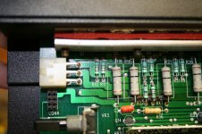
You guys got a bit confused here, just want to clarify. If you look at the picture you posted of R13 and R24 they are both 51 ohm. R24 is to the right a few components. R27 is the 750 ohm. I will look at the unit I have when I get home.
Just to clarify, the unit is a PC-150 Rev E. Probably not a good sign that they smoked. I'd say the Gate on those two devices shorted to rail. Their source side appears connected and goes south to the pass through just below VR3 marking, then turns east and lands at HB3-17. I'm hoping I can fix mine without removing the PCB, but ultimately it will happen to replace the 20yr old compound. When yours comes out, please post pics, if mine comes out first I will.
Perry - Sorry about the post concerning the caps on the input board. I haven't been active in forums, and figured I'd just give it a shot. What do you think on that blackening on the ceramic, just stained by the dielectric? Going to give it a good cleaning try it. I've got a few units that need love so I'll be around, one being a bx1500d I haven't looked at in years.
Perry - Sorry about the post concerning the caps on the input board. I haven't been active in forums, and figured I'd just give it a shot. What do you think on that blackening on the ceramic, just stained by the dielectric? Going to give it a good cleaning try it. I've got a few units that need love so I'll be around, one being a bx1500d I haven't looked at in years.
Oh god no, Perry please don't tell me the black squares and rectangles on the Hybrids are resistors! Arhhhh. And I thought the newer units with the mosfets soldered on modules that you had to torch to get off were bad.... Have a few bad traces. Time to start stranding and conformal coat.
Yea, not good. I show nothing through a few of the black pads, and one of the overpasses looks open as well (the one that looks blue, not yellow like the rest). Any insight?
Hey Scot thanks for the info. I do believe I have a shorted transistor but have not had the time to work with it lately. Hopefully when I get off of this 12hr night shift I will get it figured out. I would recommend cleaning that old thermal compound and getting some new stuff on there. Like you said its 20+ years old. Probably doing more harm than good...
Like Perry said. Start a new thread for yourself. That way it will eliminate confusion as well as help others if they encounter the same or similar problems. There is tons of knowledge and experience here and these good people are often willing to share and help you out.
Like Perry said. Start a new thread for yourself. That way it will eliminate confusion as well as help others if they encounter the same or similar problems. There is tons of knowledge and experience here and these good people are often willing to share and help you out.
- Status
- Not open for further replies.
- Home
- General Interest
- Car Audio
- Punch 150hd resistor values and possibly schematic