So while testing some subs I rebuilt the output wires for my Kicker DX1000.1 crossed for a few seconds after accidentally pulling on the cable after disconnecting from 1 sub to hook up another, 1st time I have ever done that, man what a newb move ...
I pulled all power ASAP but the damage is done, on my test bench the amp only pulls 3v and is maxing out the 2amp I have it limited too @ idle and puts it in CC mode so I’m sure it’s pull more of allowed, while trying to troubleshoot all the mosfets tested good diode wise, so with my limited experience and wanting to narrow it down to where the damage is I pulled all mosfets.
Amp powers on proper and comes out of protect with no PS mosfets installed, and the middle socket on PS mosfets bank gets 12v, which is telling me the PS mosfets are blown/out of spec sending amp into protect when they are installed on board. I’m guessing driver IC is still good as it comes out of protect and send the proper 12v to the PS mosfets.
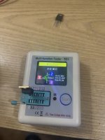
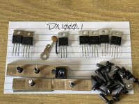
I’ve included a pic of the IRFB3077 PS mosfets connected to my cheap o meter, something must be just wrong enough with them to send amp in protect but they still test good diode mode wise and they look functional on meter but I’ve never seen a Cg reading that high on a mosfet before, are these out of spec and can you even tell with what little info this meter gives?
If they are not out of spec but throw amp into protect when installed what else could it be? Any and all info/advice would be great ...still can’t believe I got clumsy and caused those wires to cross, literally has never happened before ...feel like such a dumbass lol.
I pulled all power ASAP but the damage is done, on my test bench the amp only pulls 3v and is maxing out the 2amp I have it limited too @ idle and puts it in CC mode so I’m sure it’s pull more of allowed, while trying to troubleshoot all the mosfets tested good diode wise, so with my limited experience and wanting to narrow it down to where the damage is I pulled all mosfets.
Amp powers on proper and comes out of protect with no PS mosfets installed, and the middle socket on PS mosfets bank gets 12v, which is telling me the PS mosfets are blown/out of spec sending amp into protect when they are installed on board. I’m guessing driver IC is still good as it comes out of protect and send the proper 12v to the PS mosfets.
I’ve included a pic of the IRFB3077 PS mosfets connected to my cheap o meter, something must be just wrong enough with them to send amp in protect but they still test good diode mode wise and they look functional on meter but I’ve never seen a Cg reading that high on a mosfet before, are these out of spec and can you even tell with what little info this meter gives?
If they are not out of spec but throw amp into protect when installed what else could it be? Any and all info/advice would be great ...still can’t believe I got clumsy and caused those wires to cross, literally has never happened before ...feel like such a dumbass lol.
Attachments
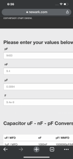
Just some info I found, spec input capacitance, which is the highest value capacitance on the data sheet (don’t know which meter is giving) is 9400pF, which is 9.4nF and if meter is saying it’s 14nF ...that’s much more then the given -/+10% usual threshold for a given spec, so if that enough to send amp into protect causing it to only pull 3v / 2+CCa? Guessing yes, from what a layman can tell anyway ...right?
Attachments

If you let the wires touch more then likely it’s the output transistors not the power supply mosfets
Ya that’s what I thought, but the amp locks up into protect soon as the PS mosfets are in circuit, and the Output mosfets test good.If you let the wires touch more then likely it’s the output transistors not the power supply mosfets
Do all of the 3077s read the same?
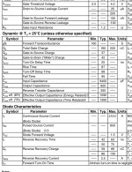
The transistor is supposed to have an RDSon of 0.0033 ohms. Your meter gives it as 0.2. If all read the same, the meter isn't likely reliable.
The transistor is supposed to have an RDSon of 0.0033 ohms. Your meter gives it as 0.2. If all read the same, the meter isn't likely reliable.
Yes they all read the same, giving me the impression they are good, yet they lock up the board and send it into protect when soldered in. I’ve already started the return process on this meter and am just going to spring for a more competent unit, this isn’t the first time it’s given a crap reading lol, you def get what you pay for 🥴 but if this spec is that much off could it possibly be the reason they send board into protect causing a 3v2+a @ idle power draw?
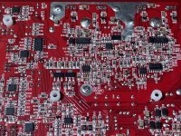
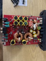
I’m going to try finding the Drive IC to see if it came out unscathed, I posted a pic of the area I’m pretty sure it’s in, Ill try looking up each til I find it. I’m still learning my ClassD circuitry 😅 Any advice on an area to concentrate on with the given symptoms? I’ve already ordered IRFB3077 replacements as well, jic.
...still can’t believe I did this, good learning experience if nothing else I guess (Im trying to see the positive side damnit, lol!)
Attachments
I'm hesitant to try to help with this amp because I'm most certainly not the best option.
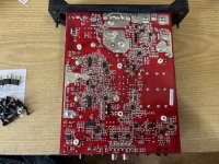
You stated that you were looking for the drive circuit. I assumed that you were looking for the PS drive but the photo you posted was of the audio section. What drive were you looking for?
Are all of the FETs in this amp the IRFB3077?
You stated that you were looking for the drive circuit. I assumed that you were looking for the PS drive but the photo you posted was of the audio section. What drive were you looking for?
Are all of the FETs in this amp the IRFB3077?
O wow, I didn’t even realize there was a difference and that each section has its own IC. So there’s a Drive circuit for output and a drive circuit for power supply, that makes complete sense, I def have a lot more reading to do on BCAE, etc 😅 there’s only 2x “IRFB3077” for Power Supply, 1x rectifier with markings “60A100CT” and 4x “FB3072” for output section and that’s it.
I would like to find the PS drive circuit, just to make sure all is good, but really I’m guessing atp, I’m assuming it’s the PS mosfets cuz when they are not on board it is not in protect, idling at 12v / .05a , but with PS mosfets installed board locks up (no other mosfets installed FYI) into protect and pulls 3v / 2+ “CC mode”. And even tho you may be winging it yourself cuz your unfamiliar with this model Perry I still trust any direction you think is a good idea. I’ll know for certain once the new PS mosfets get in tho 🙂 I can take closer more detailed pics if needed but these are just general layout pics.
I would like to find the PS drive circuit, just to make sure all is good, but really I’m guessing atp, I’m assuming it’s the PS mosfets cuz when they are not on board it is not in protect, idling at 12v / .05a , but with PS mosfets installed board locks up (no other mosfets installed FYI) into protect and pulls 3v / 2+ “CC mode”. And even tho you may be winging it yourself cuz your unfamiliar with this model Perry I still trust any direction you think is a good idea. I’ll know for certain once the new PS mosfets get in tho 🙂 I can take closer more detailed pics if needed but these are just general layout pics.
Attachments
Last edited:

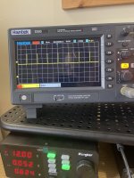
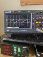
No sawtooth or square waves on L339 IC but got a sawtooth on pin4 and what looks to be a “square wave” on pin 7 (don’t know actual term) on the VR 3845B, is the voltage regulator the power supply side Drive ic? All other leads on both chips either hi/low voltage or varying sine wave.
Attachments
Are you sure that the first waveform was on pin 7?
The output FETs are IRFB3307s, not FB3072.
Do you see the square wave on the gates of the PS FETs?
The output FETs are IRFB3307s, not FB3072.
Do you see the square wave on the gates of the PS FETs?
Yes, 60khz at 12v on pin 7, which is the 3rd pin on the top row of IC 3845B, which is the same signal on the gate/3rd pin of IRFB3077, but that’s output?
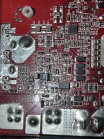
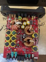
Also I thought the output side was the side near the speaker terminals like usual? 4 mosfets with FB33072 in each, and the output side was the mosfets near the power input terminals being only 2 with IRFB3077?
Wow man I had it completely backwards then, never seen that before where the fets near +\- terminals were the outputs, cuz that’s where the 2x IRFB3077 came from. Guess it goes to show never just assume 🙂 no wonder some stuff seemed off and why I thought some stuff wasn’t working right ...geez, lol. Ty Perry
pic below is what I thought it was ...lol
Attachments


Ahh ok, ty. And as far as the pinout I thought it started over at the left when going to top, like TL494, not wrapping around from right, so it’s pin6 I was getting that pulse wave reading from, which makes sense being marked Output. I just got the new IRFB3077 in so I’m going to solder them in, then continue on resolving in the other mosfets until I hit a problem or it’s back together. I’ll update soon as I’m done.
Ahh ok, I assumed on the TL494 and just ran with it with all others without even checking a data sheet. I’ll make sure from here on out to double check and make sure that what I am typing is actually coherent to others so they can understand, I don’t want to get in that bad habit so early on just assuming and/or guessing.
Also, same exact problem with brand new PS mosfets, 3v/2a+ CC protect mode on when only the 2x IRFB3077 Power supply mosfets soldered in. That seems so odd to me that it comes out of protect with no mosfets in, but when even brand new ones soldered It kicks into protect and screws up power draw ...I still don’t fully know the power path of a class D circuit so the process of elimination is still lost on me, I’m going to research the above that you suggested and go from there.
Ty Perry
It should be expected that replacing perfectly good FETs would make no difference.
Some of the power supplies of this configuration (flyback) don't like to power up without the rectifier. That said, if there is another problem, installing the rectifier won't make a difference until the other problem is resolved.
Did you check the rectifier to confirm that it was OK?
Some of the power supplies of this configuration (flyback) don't like to power up without the rectifier. That said, if there is another problem, installing the rectifier won't make a difference until the other problem is resolved.
Did you check the rectifier to confirm that it was OK?
Ya just assuming the PS mosfets were bad/the problem because the amp locked into protect when they were soldered in, even tho the cheap o meter also showed they were still good, is just another reminder ...and it cost me money this time too to learn not to guess/assume :/ discouraging, but all a learning process I guess.
i should really learn the common Class D power supplies as well, didn’t know this was a “flyback” system or even what that is, and no I didn’t even test the rectifier, again I assumed it was ok because I remember hearing more then once they are usually ok/tough as tanks when power supply blows, I gota stop doing that. I’ll look into it now.
I apologize Perry, not trying to make this so hard by not even doing the basics. I’m going to read up/search more on this amp and it’s power supply, and test the rectifier as well. I’ll report back once I have a better grasp on it. Ty for your input, I do appreciate it more then you know, really.
Most power supplies in car amps are the push-pull type. The FETs in a push-pull supply alternately switch on and off foe each bank of FETs.
The flyback (some refer to as a boost supply) grounds the winding of the transformer and then releases it. When the winding is released, the energy stored in the transformer is released and the result is a voltage greater than the 12v input voltage which forms the rail voltage.
What are the output ICs in this amp? IRS20957?
Sorry for the slow reply, decided to step back and dig in more on the very basics and whatnot, binging on your site and other reliable sources/YT vids from good repairers. I was bouncing between amps overwhelming myself to the point I’m posting but not giving coherent information 😅 Nothing ended up being wrong with this amplifier, I just wasn’t giving it enough power on my test bench or try pulsing the remote to help it along with the limited power. Mad embarrassed about that, simple mistakes that could have prevented a lot of soldering, wasting some money, and digging in looking for problems that weren’t there wasting your time, I apologize for that, def a learning experience if nothing else. Decided to tackle the ZX750.1 since the magnet wire finally got in and I’ve made great headway and am now at the output section. I’ll be posting an updated thread as I don’t think I’ve done that yet, been meaning to to help others as well. Thx for everything Perry and again my bad bro 😅
- Home
- General Interest
- Car Audio
- Pulled a newb move and my output wires crossed on DX1000.1 ...