Psychosis Headphone Amp:
Stereo single 100mm x 80mm board.
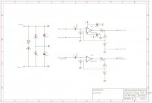
i have incorporated RJM's X Reg as the power supply.
Rectification is on board.
Duel opamp with buffer and Jfet Cascode to bias into Class A.
Headphone socket on board.
Volume Pot on board.
Zobel Filter Daughter Board (still in the works).
all opinions and help more than welcome 😉


View attachment Psychosis_v1.zip
Stereo single 100mm x 80mm board.
i have incorporated RJM's X Reg as the power supply.
Rectification is on board.
Duel opamp with buffer and Jfet Cascode to bias into Class A.
Headphone socket on board.
Volume Pot on board.
Zobel Filter Daughter Board (still in the works).
all opinions and help more than welcome 😉
View attachment Psychosis_v1.zip
Update:
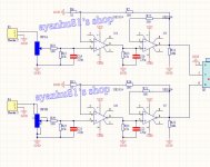
I have added jumpers/shunts (circled in red) to change the configuration of the amplifier.
Leave J1R/L open, remove BUF-R/L and shunt J2R/L will give the classic Cmoy design.
As above but shunt J1R/L will add the Jfet cascode to bias into class A.
As above but remove J2R/L shunt and add BUF-R/L will give intended design.
Next up is designing some daughter boards that will plug into the BUF-R/L DIP-8 sockets to replace BUF-R/L for discrete diamond buffers. If I'm careful with the placement of parts i can add the Zobel network boards as well and have them 'snap off'.
I'm all for clean schematics but being able to fit it all on screen without resorting to a magnifying glass has its perks, too...
You have placed the Class A bias current sink after the buffer, why? (Usually you'd bias the opamp output stage into class A if anything.)
Also, using these big-*** speaker crossover film caps as input coupling caps? You know what kind of parasitics they have? That's just oscillation waiting to happen, not to mention the crosstalk. Hint: You do not need a 400 VDC rating in this application, and ordinary Panasonic and WIMA films tend to be perfectly fine if bipolar or low-leakage electrolytics aren't your thing.
thanks for the feedback sgrossklass.
if you click the schematic/layout pic's they will enlarge to mahoosive 🙂 well it does at this end.
this is why i'm still a noob at this, my reasoning was that if i put the class A bias after the buffer it will make sure everything is in class A (kept switch on) including the buffer. i guess i'm wrong. i'll go ahead and see if i can put the bias on the opamp output stage.
i was under the impression that those big crossover caps were the norm and the thing to do, i'll add some pads so i can also try WIMA caps.
so apart from the above, how is the idea looking. right or wrong direction?
Update:
decided that its easier to just use a mil-max 575-99911113 across the Buffer socket instead of the jumpers to test with the Buffer out the socket but keep the opamp in the feedback.
removed the Cascode jumpers and repositioned them where the Buffer jumpers were and added one more pin so i can test the Cascode in the feedback, input or out of circuit mode.
re-routed the negative supply for the Buffer as i was not happy with the way it was.
added a 5 way connector at the AC input to incorporate a GND connection for the board to chassis if needed.
designed a discrete diamond buffer but ended up not liking the way it was on the daughter board so that idea is out the window. i'm still toying with the idea of using a diamond buffer aka, RJM Audio Sapphire 2.0f as i could fit it onto a very small daughter board.
i would like to be able to put the Buffer inside or outside the feedback loop with jumpers but as yet have not been able to physically fit the jumpers on the board so inside the loop it stays.
forgot about the wide bandwidth mode for the BUF634 so its now incorporated.
looking at data sheets for different opamps i noticed that a AD and BB use different trim pins on the opamps but the good news is that BB use pins 1-8 with 5 being NC and AD use pins 1-5 with 8 being NC. now added a trace from 5 to 8 so both AD, BB can be used and still be trimmed via the variable resistor. if push comes to shove i can always cut either pin 5 or 8 off the opamp.
looking at data sheets for different opamps i noticed that a AD and BB use different trim pins on the opamps but the good news is that BB use pins 1-8 with 5 being NC and AD use pins 1-5 with 8 being NC. now added a trace from 5 to 8 so both AD, BB can be used and still be trimmed via the variable resistor. if push comes to shove i can always cut either pin 5 or 8 off the opamp.
I'm sorry, I did not understand you. IMHO the scheme CMOY at the line Audio IN should be capacitors (C1L and C1R). Or am I wrong?Leave J1R/L open, remove BUF-R/L and shunt J2R/L will give the classic Cmoy design.
Attachments
'Cmoy' is the circuit. C1L and C1R are the input coupling caps. C1L/R the 'symbols' are replaced with 'pads' on my schematic but marked with an outline on the board.
Sorry, I do not quite understand the work of the op-amp ;(. I did not notice on your schematic input coupling caps, and therefore wrote ... 😕
the input opamp is basically a classic cmoy design which leads to a Buffer (BUF634) as the output, both are in the same feedback loop. there is also a jfet cascode to bias the circuit into class A. the cascode can be configured so it is in the feedback loop, input loop or omitted out the circuit all together (schematic needs updating).
my intention with this board is to hear the effects of each individual type of design and as such will have a lot of jumper pins added to the board for configuration. the board is not intended as a 'finished working design' but more of a 'play and see what happens design' for instance using outboard breadboard to design a discrete buffer for instance but still be powered by and part of the main circuit board. its to help me (and others if they wish) to understand more about basic headphone audio circuits.
the design is based around a lot of information from tangentsoft.net and RJM Audio's Sapphire headphone amp and other design ideas from him such as the x-reg.
its not so much adding to the schematic that is the problem but adding the component to the already crowded board. my intention was to be able to take the buffer in and out of the feedback like (R71-72) in the schematic above but i cant physically fit it on the board.
...my intention was to be able to take the buffer in and out of the feedback like (R71-72) in the schematic above...
Hello bibio,
I would certainly recommend jumpers to enable/disable the class-a bias option. I found it did not suit my ears.
hi mlackey, i have added jumpers for the cascode.
there are 4 sections. CMoy, Buffer, Cascode, Zobel. the CMoy is the base amp circuit and any of the other three can be added in or out of the circuit for any configuration of them.
i really would have loved to been able to take the buffer in and out of the feedback but i cant find a path for the jumpers.
i'm still wring up a BOM and how to.
- Status
- Not open for further replies.
- Home
- Amplifiers
- Headphone Systems
- Psychosis