Hello everyone,
I am making a trial 12V DC power supply with a transformer, and choke I already had and some salvaged capacitors from an old defunct project - so no investment apart from some diodes, really mostly for learning.
I have not yet got back my old 15V transformer that a friend is using so I found an old one wall wart 15v to start to understand and explore.
Well this is the current circuit I am 'comparing' simulation from measured
(for my real 12VDC I am going to build I will use the twin 0-15 transformer I have in series to give 30vAC I think to be able to get the noise down, according to simulations)
The current draw is 340mA Anyway this is the circuit and below is the measurements from an oscilloscope on DC and AC coupling.
The crazy thing is in actual measurement that last filter ADDS NOISE!! and the overall noise is way off e.. VC2 27mV predicted and 232mV measured?
Any thoughts?
VC1 17.1V DC and 5.3v p2p
VC2 13.5V DC and 232mV p2p
VC3 8.86V DC and 720mv p2p
Tx & choke data are correct?
I normally use 10.000 mS first at 0 S to see how fast is the PSU, 2nd at 3 or 4 S to see the ripple and 3rd at 10 S to be sure is the same ripple like 2nd measurement.
I normally use 10.000 mS first at 0 S to see how fast is the PSU, 2nd at 3 or 4 S to see the ripple and 3rd at 10 S to be sure is the same ripple like 2nd measurement.
Last edited:
If you measure more noise after the last filter, that is a measurement error.
The p-p voltage ripple on C1 is way too large. Increase C1 so that the p-p ripple is less than 1V.
That large ripple is probably coupling into your measurement through poor wiring layout.
The p-p voltage ripple on C1 is way too large. Increase C1 so that the p-p ripple is less than 1V.
That large ripple is probably coupling into your measurement through poor wiring layout.

Yeah I have been using the initial from 0 to see the speed and any ringing from the choke, and then 4S or later to see the steady state.Tx & choke data are correct?
I normally use 10.000 mS first at 0 S to see how fast is the PSU, 2nd at 3 or 4 S to see the ripple and 3rd at 10 S to be sure is the same ripple like 2nd measurement.
What sort of response time should I consider fast to get to full voltage, and slow?
Fast 0 to 2-3 seconds to get full voltage.
Slow 4 or more seconds.
The choke value is calculated or is the one you have on hand?
Slow 4 or more seconds.
The choke value is calculated or is the one you have on hand?
Vripple = I/(6.24 x 120)C
so it is easy to see that the higher the C, to lower the ripple voltage is..
the higher I also raises the ripple voltage...
so it is easy to see that the higher the C, to lower the ripple voltage is..
the higher I also raises the ripple voltage...
Use a stepped load current to assess the power supply response to a transient load change (eg. from an amplifier type load). Your existing circuit indicates a significant damped ring at about 4Hz.
You need to be careful with probe grounding, and power supply grounding, when trying to assess secondary side ripple and noise, as indicated by rayma. Did you ground the secondary side or leave it floating. Did you use a probe with a long gnd lead and clip, and where did you connect the clip to? Is the 'noise' just low frequency (twice mains frequency) ripple, or higher frequency noise, that is giving the p-p signal voltage?
You need to be careful with probe grounding, and power supply grounding, when trying to assess secondary side ripple and noise, as indicated by rayma. Did you ground the secondary side or leave it floating. Did you use a probe with a long gnd lead and clip, and where did you connect the clip to? Is the 'noise' just low frequency (twice mains frequency) ripple, or higher frequency noise, that is giving the p-p signal voltage?
Thanks everyone, all your wise input is very much appreciated as I slowly go up the learning curve. 😉
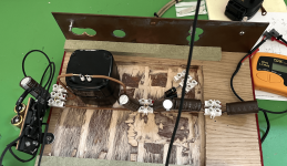
This is the current model I am measuring and simulating
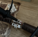
I am measuring with a 1x probe and spring clip ground.
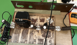
This is the actual breadboard, I measure at the terminal block connections
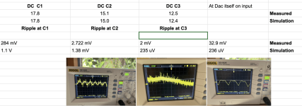
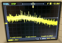
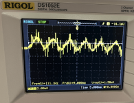
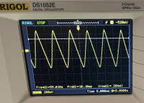
and these are the results I measure (the output of the 12V DC powered DAC is not connected to anything or grounded)
What is strange is the increase in noise at the DAC itself as when I measure at the input jack at the DAC rather than the terminal block at the start of the DC power lead it increases a lot.
See images, hopefully this makes sense
Rich

This is the current model I am measuring and simulating
I am measuring with a 1x probe and spring clip ground.
This is the actual breadboard, I measure at the terminal block connections
and these are the results I measure (the output of the 12V DC powered DAC is not connected to anything or grounded)
What is strange is the increase in noise at the DAC itself as when I measure at the input jack at the DAC rather than the terminal block at the start of the DC power lead it increases a lot.
See images, hopefully this makes sense
Rich
Attachments
Perhaps add a photo of the scope and the 1x probe, as I can't see it in the photos. Where is the transformer?
Can you confirm the first photo of scope show 10ms period ripple of about 2.4mVpp?
Is the horizontal axis 5ms for the 2nd photo as well? If so then perhaps slow down the timescale to see what the signal is that is << 20Hz.
Is the horizontal timescale of the 3rd plot at 500ns ? The plot seems to show a 550kHz signal, which appears to be from your DAC device ?
Have you had the DAC device connected as load for all your test results? Or did you use a resistor load for test results?
I think @trobbins found the answer to the original question: an ideal constant current source is too simple a model for the DAC, it doesn't model the supply current variations of the DAC that actually cause most of the output ripple.
I have another question: don't you blow up your DAC the moment you put it in standby or some other low-power mode? The output voltage of the supply will increase to about 20 V without load (could be 22 V when the mains voltage is near its maximum). With 30 V AC, it will be over 40 V.
I have another question: don't you blow up your DAC the moment you put it in standby or some other low-power mode? The output voltage of the supply will increase to about 20 V without load (could be 22 V when the mains voltage is near its maximum). With 30 V AC, it will be over 40 V.
I currently use the DAC by turning it on and off by the mains plug switch and never change a setting on it. I use a switch mode power supply (4A Lacie model) and have tried numerous cheap linear power supplies, but the SMPS sounds better. I wanted to try better linear power supplies to see
It's a very basic but amazing sounding DAC with modifications - this one shown in the link, and the mods recommended, I use it with USB input via an Ethernet Bridge.
https://jeffsplace.positive-feedbac...nture-from-yazaki-san-the-iphone-adventure/8/
It's a very basic but amazing sounding DAC with modifications - this one shown in the link, and the mods recommended, I use it with USB input via an Ethernet Bridge.
https://jeffsplace.positive-feedbac...nture-from-yazaki-san-the-iphone-adventure/8/
- Home
- Amplifiers
- Power Supplies
- psud2 simulation does not match measured and measured look weird? any ideas