Perhaps an odd (silly? stupid?) question, but I need a bit of clarification regarding entering data into PSUD2. I have done a Google Advanced Search in general, and on here, seeking an answer, (yes, I’ve read the Tim Robbins instructions, too) but can’t find one.
So here goes …. With a center tapped transformer, you enter the voltage from the CT to one side of the secondary, as well as the resistance from the CT to one side of the secondary (or across the secondary and divide by 2). But what about the current?
As an example, I have a 900 volt CT plate transformer that’s rated for 250ma. In PSUD2 I enter 450 in ‘nominal output’, but for current is it .25 amps or .125 amps? It seems sensible to go with .125 amps, and all tube rectifiers list their allowable current per plate, so that fits, too. However, I’d like to be certain I’m doing this correctly.
PSUD II runs on spice and models the transformers as voltage sources with equivalent AC resistance.
In circuit analysis AC sources are capable of unlimited current, whereas current sources are capable of unlimited voltage. (Somewhat of an oversimplification)
You can drop your PSUD2 file here if you like il give you some pointers.
I actually didnt answer the question, transformer current rating is of no importance in a PSUD simulation is my guess, I dont know whats running under the hood.
What the simulation will tell you, is the peak current draw from the rectifier tube. You can keep the stock 200mOhm ESR for the capacitors, it doesnt really matter if its fed by a high impedance source like a rectifier tube.
Cheers,
V4lve
Last edited:
PSUD II runs on spice ......
I don't think it does use SPICE; I think Duncan invented a unique engine.
PSUD "asks" for current only in its "Regulation" dialog, which estimates Ohms from Amps and Regulation.
Yes, I'd rather gathered that idea somewhere myself, and I think improvements were made for the more recent release..I don't think it does use SPICE; I think Duncan invented a unique engine.
@ V4lve lover, your posts seem to have a lot of white space and are cumbersome to scroll through. Browser issue maybe?
prairieboy, the transformer secondary current rating is not explicitly entered in to PSUD2 - you need to keep any such limit in mind when looking at simulation results, but be careful about whether a transformer spec is for the rms winding current as some vintage transformer data identifies max DC load current.
By simulating a load resistance, the simulation will calculate the winding current for that circuit arrangement. So you need to confirm winding rms current does not exceed the transformer ratings, for a maximum dc output situation that suits you.
By simulating a load resistance, the simulation will calculate the winding current for that circuit arrangement. So you need to confirm winding rms current does not exceed the transformer ratings, for a maximum dc output situation that suits you.
I think i made that post on my phone, a 2x2'' screen right before the sandman got me.@ V4lve lover, your posts seem to have a lot of white space and are cumbersome to scroll through. Browser issue maybe?
As far as i know, PSUD-2 is a spice runtime environment. One thing that it likely doesn't account for completely is the inductance of the transformer, because this requires you to measure this with a LCR. So if you look at the charging peaks through the capacitor, they look somewhat exaggerated compared to real life.
cheers,
V4lve
prairieboy, the transformer secondary current rating is not explicitly entered in to PSUD2 - you need to keep any such limit in mind when looking at simulation results, but be careful about whether a transformer spec is for the rms winding current as some vintage transformer data identifies max DC load current.
By simulating a load resistance, the simulation will calculate the winding current for that circuit arrangement. So you need to confirm winding rms current does not exceed the transformer ratings, for a maximum dc output situation that suits you.
I didn't think this was that obtuse a question. To clarify (or not) what goes in the little box in the upper right hand corner that says 'current'? Do I enter the current rating of the transformer - 250 ma in this case - half of that amount, or make up some number based on the celestial settings? PSUD needs some value to do the calculations for the two lower boxes.
Attachments
Since the secondary halves are in series, the current through each half is exactly the same as the current thorough the whole secondary.But what about the current?
You don't have to divide anything by 2.

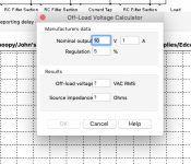
Ahh, I see your concern better now. I normally come at it from not knowing the manufacturer's ratings (the rated output AC voltage when supplying rated current), and only knowing the off-load winding voltage and winding resistances (which I measure and are inserted in the other 'Source Impedance calculator' embedded in PSUD2 and entered by clicking on the lower "..." box in the 'Edit transformer properties' pop-up.
So firstly you need to confirm what the manufacturer has specified, and that can be ambiguous, especially for full-wave rectifier type winding configurations. For a single secondary winding which would be used for a bridge rectifier or doubler, the manufacturer likely specifies the winding loaded voltage when supplying the rated rms current. For a full-wave configuration that all becomes a bit messy, and is likely why vintage ratings were often based on a secondary winding providing a certain winding voltage for a rated DC output current with either a capacitor or choke input (although sometimes the manufacturer inconveniently didn't specific choke or capacitor filtering).
If the manufacturer rating is not explicit (do you have a link?), then you could follow the Off-load voltage calculator for entering parameters with what is possibly the parameter values, or revert to the other calculator and make measurements of off-load voltage and winding resistances.
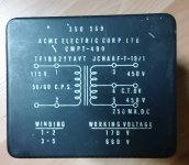
Yeh that PT has the vintage style of current rating (250mA DC), and as is common it doesn't identify whether that is for capacitor or choke input. So perhaps best to just go the measurement path for PSUD2 parameters, and assuming you have a capacitor input filter configuration then keep the B+ dc load under 250mA.
One nuance is that the PT is probably vintage enough to be designed for (just) valve rectifiers, where peak winding current is lower and rms heating of the winding is less when compared to a ss diode rectifier modern application with plenty of first filter capacitance.
One nuance is that the PT is probably vintage enough to be designed for (just) valve rectifiers, where peak winding current is lower and rms heating of the winding is less when compared to a ss diode rectifier modern application with plenty of first filter capacitance.
It's from an RCAF (Royal Canadian Air Force) modulator supply. My old notes on it say it had a choke input (I assume the 6.25 H, 205 ma, 620 volt Acme choke I have. The other Acme chokes are rated for 700 ma at either 1000, or 1600 volts. I'll guess they were used with the 2000 volt CT Acme transformer) And yes, you're:correct in assuming a valve rectifier.
...As far as i know, PSUD-2 is a spice runtime environment....
Explicitly stated to not be SPICE.
C:\Program Files (x86)\PSU Designer II\help\html\index.htmlQ: Why are there sometimes small glitches on the rectifier voltage?
A: These are caused by short cuts taken in the simulation. A dramatic speed improvement is made over alternative simulators such as SPICE, and this is the price that is paid for the extra speed.
prairieboy, if the PT 250mAdc rating was valid for capacitor input filter, then the winding current may be rated for circa 300mArms. If it was just rated for choke input filter, then the winding may only be rated for circa 180mArms. There in lies the concern, as the winding power dissipation is nearly 3x as high for cap input.
I hope this doesn't hijack the OP's thread. I am having similar problems figuring out PSUD.
I have built the attached circuit and get a B+ under load of 197V. However PSUD calculates a B+ of 417 or so.
Clearly I am entering something wrong. Any help would be appreciated.


 Thanks in advance.
Dave
I have built the attached circuit and get a B+ under load of 197V. However PSUD calculates a B+ of 417 or so.
Clearly I am entering something wrong. Any help would be appreciated.
Thanks in advance.Dave
But the transformer literature says 360V nominal 180-0-180. Am I not understanding what this indicates?Your transformer provides 180VAC but you entered 360VAC in PSUD2.
Jan
Look at the schematic. There are two 180V secondaries. There is a double-phase rectifier. One diode conducts when the sinewave goes up, the other when the sine wave goes down.
That's why it is called double-phased, and that is why the transformer is specified as 180 - 0 - 180.
Did you want a Vout based on 360VAC, like you entered in PSUD2? In that case you need to use a single rectifier and use the two secondaries in series so you have 0 - 360V.
Jan
That's why it is called double-phased, and that is why the transformer is specified as 180 - 0 - 180.
Did you want a Vout based on 360VAC, like you entered in PSUD2? In that case you need to use a single rectifier and use the two secondaries in series so you have 0 - 360V.
Jan
- Home
- Amplifiers
- Tubes / Valves
- PSUD2 Question